
Learning Resources
Lesson
Technical drawings look the same regardless of how they were created. An isometric will have the same type of lines and in the same positions. An orthographic will use the same alphabet of lines and the same locations for views, dimensions and so on.
There are three ways to create technical drawings
- sketching
- using mechanical drafting instruments
- using computer assisted drawing (CAD) software
Technical Drawing Tools
Sketching Tools
Sketching tools consist mainly of paper, with or without grid lines, and a variety of pencils. Pencils are made with the lead (graphite) made in different degrees of hardness. The range is from 6B (very soft) to 9H (very hard). HB is the transition from 1B to 1H. Sketching pencils are usually in the H to 3H range. Standard pencils are HB and are easy to smudge with your hand while you are drawing with them. In addition, they are usually inconsistent in the composition of the graphite, with hard and soft spots. 6B creates soft black lines, and is very easily smudged. 9H creates sharp, very light lines, and is almost impossible to smudge. H, 2H, and 3H are good compromises giving good sharp lines, but making it more difficult to smudge.
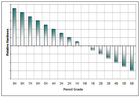
Figure Pencil Grades and Relative Hardness, from hardest (9H) to softest (6B)
Very soft is at the bottom of the chart and very hard is at the top, with HB being general purpose. The Hs are mostly used for technical drawings. The Bs are mostly used for drawing and illustrating.
The figure below shows the following samples
- Staedtler HB drawing pencil
- Lee Valley H drafting pencil
- Unique 4H drafting pencil
- Berol 0.5 mm mechanical drafting pencil (2H lead)
- Staedtler 780 mechanical drafting pencil (3H lead)
- Staedtler 3H drafting pencil
- Bic 0.5 mm general purpose mechanical pencil (HB lead)
- Staedtler plastic eraser (low smudge, easy to clean)
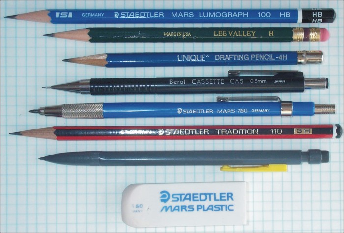
Figure Drafting/Sketching Pencils
Sketching is the most frequently used technical drawing method. It allows rapid drawing development, quick changes to the drawing, and is the easiest and most direct way to create technical drawings.
Mechanical Drafting Tools
The primary mechanical drafting tools are
- drafting pencils (see above)
Usually in the range H to 4H for pencils and mechanical pencils - drafting pens (see also Colours, and Dick Blick)
Used for inking the lines to make them more permanent, or to aid in reproduction. There are two basic types: the bow pen and the technical pen. The bow pen holds ink between two metal strips which touch at the drawing tip. The technical pen holds ink in an internal reservoir and dispenses it through a hollow needle-like nib. Sizes range from 0.013 mm to 5mm. - 30-60-90 and 45-45-90 triangles
Generally made from plastic, these triangles come in various sizes and have the most common angles used in technical drawings (30, 45, 60, and 90 degrees). Triangles are used almost exclusively with T-squares or with parallel rule equipped drawing boards - protractors
These come in various sizes. The larger the size, the more accurate the measurement. - drafting instruments set
This comes in a variety of configurations of sets of assorted sizes and types of compasses, bow compasses and bow pens. Compasses generally use short 3mm 2-3H leads from mechanical drafting pencils. - T-squares, parallel rules
Both these tools are used to draw horizontal lines, or as the baseline for drawing lines with triangles and templates.
The T-square is T shaped. The head of the T slides along the left or right edge of the board, ensuring that lines drawn along the blade of the T are parallel to each other.
The parallel rule has fine cables running through pulleys inside the rule and a attached to the corners of the board, ensuring that it is always parallel as it moves up and down the board. - drafting machines
Drafting machines are devices with a drafting head that can be positioned anywhere on the board. The head has two blades, placed at right angles to each other. They have a built-in protractor and can be set and locked at any angle. Once set, they can be used to draw parallel lines anywhere on the board. - scale rules
These are triangular in cross section, with 6 edges, each of which has a different scale. They are available in metric and imperial (feet) scales. Scales are important, since most drawings are of objects much larger, or much smaller than the actual drawing. - erasing shields
These are made of very thin metal and are used to precisely erase parts of the drawing without disturbing adjacent parts. - templates
Templates are flat plastic pieces with precision cut-outs. There are (or used to be) hundreds of templates available. There are symbol sets for things like electrical, plumbing, appliances, welding, and so on. Others are used for standard items on house plans such as window and door openings, and stair risers and threads. Templates are made to scale in both imperial (feet/inches) and metric measure. - french curves, flexible curves
French curves are precision plastic templates with a variety of compound curves. They are used to draw non-circular curves.
Flexible curves are plastic extrusions with a lead and spring metal core. They can be bent to a variety of shapes and used as drawing guides. - drafting tables and boards (see also Tables)
This is the foundation for all drafting activity. The board has to be flat, perfectly rectangular (900 corners), and have a smooth drawing surface that is not too hard. Since paper is usually attached with tape or art gum, it also has to have an easy to clean surface.
Surfaces are generally made from wood, or wood composites covered with a plastic laminate on both sides. The drawing surface is covered with a self-healing plastic (much like the cutting boards used in sewing) that can be quickly replaced.
Computer Assisted Drafting Tools (CAD)
CAD tools provide a highly precise means of creating technical drawings. In addition CAD tools offer a range to drawing features not easily managed with mechanical drafting, including
- libraries of symbols
- reusable parts in a drawing
- work simultaneously in orthographic and isometric
- generate perspective drawings from orthographic drawings
- generate fully shaded 3D renderings with animated fly-throughs
- semi-automated creation of extension and dimension lines
- automatic creation of parts lists from a database (placing a wall on a floor plan, for example, causes the program to create a list of wall framing parts such as bottom and top plates, wall studs, and jack studs and headers for window and door openings)
- use of grids and snap to grids for precise placement of lines and symbols
- a variety of trimming tools to fit one part to another or trim (erase the section outside) objects with other objects
While CAD tools don't require the development of mechanical drawing skills that are required for mechanical drafting, or even sketching, they do require the same level of understanding of technical drawings. In addition, the software often has a steep learning curve. As with all technical drawing, a sound understanding of geometry and construction of geometric shapes is required. Technical drawings frequently use
- translations, transformations and rotations of objects
- rectangular and circular arrays in 2 dimensional (2D) and 3D space
- detail drawings that show hidden features.
CAD is often connected directly to Computer Assisted Manufacturing (CAM). CAM machines can paint, cut, weld, mill, join, and turn material ranging from plastics to metal to fabric. CAD/CAM systems are used to automate fabrication of parts and assemblies in manufacturing plants ranging from micro-electronics (for example micro-processors) to aircraft and ships (for example, CADKey was created as a 3D CAD program to automate production of aircraft parts)
While Corel Draw can be, and frequently is, used to create technical drawings, it is not a CAD program. It does not provide the automated features of CAD programs. Technical drawings frequently require parallel lines, for example, and CAD allows drawing with parallel lines set at any required spacing. They join properly at corners and intersections. In other drawing programs these things have to be manually created.
CAD programs, ranging in cost from thousands of dollars to less than $100, include
- AutoCAD
- CADKey
- AutoSketch
- DeltaCAD
- TurboCAD
If you wish to experiment with CAD, the following programs can be downloaded.
- DeltaCAD 45 day demo Fully functional for 45 days, then it stops. Click the download link
- TurboCAD Free version. See the images below. Scroll down to the selection below. Click on the drop down arrow next to Select your Download, and select Never Expires. Click on Go and follow the instructions.
Figure TurboCAD LE download
Figure Never Expires selected


Further Information
- Drafting pencils and lead holders at http://www.leadholder.com/ (lots of images)
If Design Technology 2109 is offered in your school, have a look at the texts on architectural drafting.
Activity
Assigned activities
The purpose of this activity is to use computer tools to create technical drawings.Using the drawings in the previous activity
| Oblique
|
View the videos at the left if you need help. You can get additional Corel Draw tutorials at |
|
|
Test Yourself
There is no self test for this lesson.