
Learning Resources
Lesson
How drawings are made
Technical drawings can be created in a variety of ways.
- sketching (free hand drawing)
- using drafting instruments
- using CAD or other computer based tools
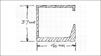
Figure Technical Drawing Sketched
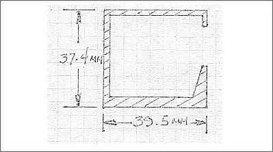
Figure Technical Drawing using Drafting Instruments
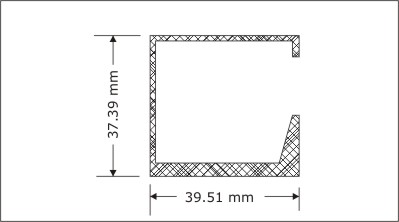
Figure Technical Drawing using CAD
Go to page b Reading a Drawing - Lines
Reading a drawing
Regardless of method, technical drawings are immediately recognizable by the types of lines, how they are drawn, and the organization of the content
Reading lines
Lines are the basic building blocks of a technical drawing. They are identified by particular characteristics as well as where and how they are used in a drawing. Generally called the alphabet of lines, the list includes
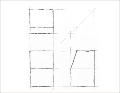
- Construction Lines. Construction lines are used to block out the parts of a drawing. They are used in sketching (free-hand drawing) and drafting (using drawing instruments). Construction lines are drawn over or are erased. For that reason they are usually drawn very lightly so that the pencil leaves no indents in the paper.
Figure Construction Lines
- Visible Object Lines. Visible object lines show the visible edges of objects. They are sharp, clear, and clean lines that will be part of the final drawing. Note that the construction lines are still in the drawing below.
Figure Visible Object Lines
- Centreline. Centrelines are dashed lines with alternating short and long dashes. They are used to indicate the centre of an object that is symmetrical. They are sharp, clear, and clean lines that will be part of the final drawing. They are usually used to show where the centre of a feature is located e.g., the centre of a circle. They are often used in conjunction with measurements. When centrelines meet, they cross on the short dashes.
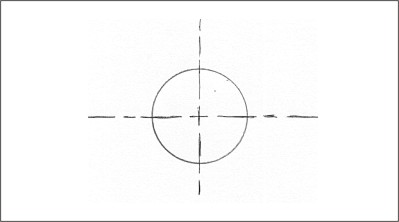
Figure Centre Lines
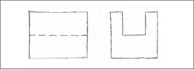
- Hidden Object Lines. Hidden object lines are dashed lines that show where the edges of objects would be if you could see them - i.e. if they were not obscured by another part of the object. They are sharp, clear, and clean lines that will be part of the final drawing. The spaces are usually 1/3 as long as the dashes. When 2 hidden object lines meet, they always meet with 2 dashes. If 2 hidden lines cross, the intersection is centred on the dashes.
Figure Hidden Object Line
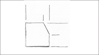
- Extension Lines. Extension lines are used to visually extend an edge or side so that measurements may be included on the drawing. They are sharp, clear, and clean lines that will be part of the final drawing. An extension line does not physically touch the edges of the object, but is drawn close enough so that it is obvious which edge it is associated with.
Figure Extension Lines
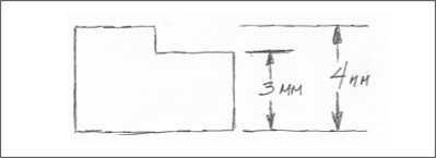
- Dimension Lines. Dimension lines are used to indicate measurements on a drawing. They are sharp, clear, and clean lines that will be part of the final drawing. Dimension lines usually end in arrow heads that touch the extension lines. They may be broken to allow room for the measurements, as shown below.
Figure Dimension Lines
Dimension lines can take any of the following forms. Only one method would be used on a drawing. Methods are never mixed.
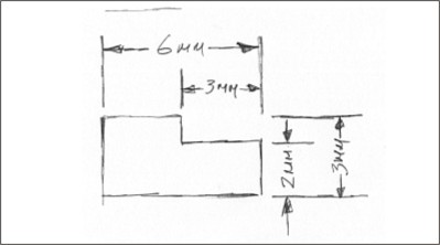
Figure Aligned Dimensions
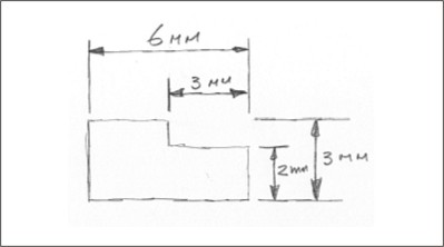
Figure Unidirectional Dimensions
Go to page c Reading a Drawing - Perspective
Reading perspective drawings
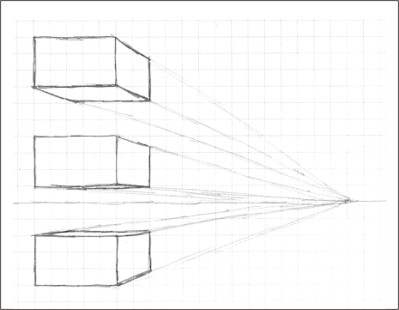
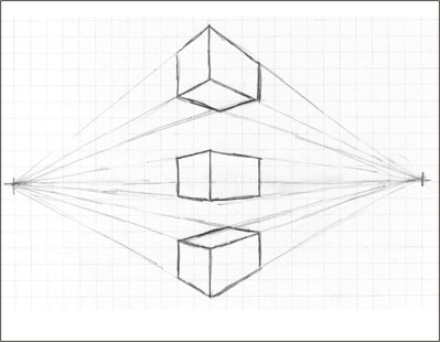
While perspective drawings are rarely used as technical drawings, it is important to know the relationship between perspective and technical drawings. Perspective drawings show the object in 3 dimensional form. Just like in real life, or in a photograph, objects in perspective drawings appear to get smaller as they get further away. The techniques for creating perspective drawings follow a number of straight forward principles. The drawings can get complex very quickly, and are time consuming to draw. The examples below show how a simple box appears in one-point, two-point, and three-point perspective.
Figure One-point Perspective
Oblique drawings are similar to two-point perspective drawn below the horizon line, but do not use vanishing points.
Figure Two-point Perspective
Isometric drawings are similar to two-point perspective drawn below the horizon line, but do not use vanishing points.
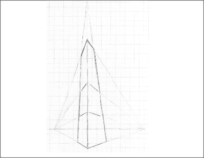
Figure Three-point Perspective
There is no technical drawing that approximates three-point perspective.
Go to page d Reading Drawings - Oblique
Reading Oblique Drawings
Oblique drawings are a form of technical drawing called pictorials that show the object as a 3-dimensional presentation. It shows the front of the object in plane view. The depth of the object is shown by projecting the sides at a fixed angle. The projected are always parallel to each other. The back edges are parallel to the front edges.
Figure Oblique Projection
There are two types of oblique drawings
- cabinet projection, which can have the sides angled at 450 or 600. The front is drawn full scale, and the sides are drawn at 1/2 scale.
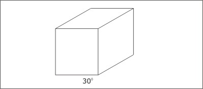
- cavalier projection, which has sides angled at 300. The front and sides are drawn full scale.
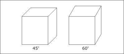
Figure Cabinet Projection (450 and 600)
Both boxes have the same dimensions. Front dimensions are shown to scale. Projection dimensions (depth) are shown 1/2 scale.
Figure Cavalier Projection
All dimensions are shown full scale. This is the same size box as shown in the cabinet projections.
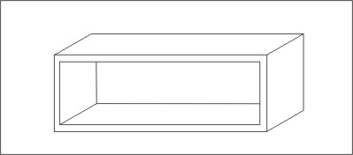
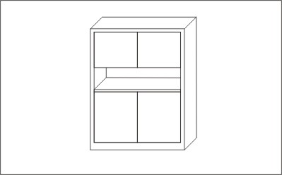
Oblique drawings are used instead of one-point perspective because they are easier to draw, and also take far less time to draw. The figure below shows a typical application of a cabinet projection.
Figure Cabinet Projection
Oblique has been mostly unused in recent years. Instead, isometric drawings are favoured.
Go to Part e Reading a Drawing - Isometric
Reading Isometric Drawings
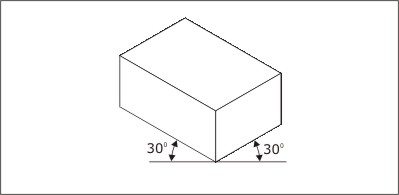
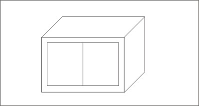
Isometric drawings are another form of pictorial technical drawing. They are used instead of two-point perspective, but are much easier to draw. A rectangular box is drawn in isometric form with all edges either vertical, or at 30 degrees to the horizontal, as in the figure below.
Figure Isometric Drawing
The faces of an object in an isometric drawing are labelled by their location.
Figure Faces of an Isometric Box
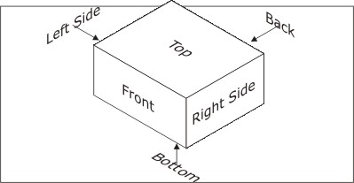
The labels are independent of the object that is drawn, or of the parts of the object.
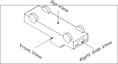
Figure Isometric Views
In this figure, the object is an upside down truck. The front view is actually the side of the truck, the top view is the bottom of the truck, and the right side view is the front of the truck. Remember, the labels refer to the position in the drawing and have nothing to do with what the drawing is about.
Isometric techniques can be used to reproduce quite complex objects. A few examples are shown below
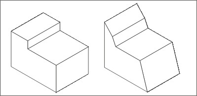
Figure Isometric Block With Cut-outs
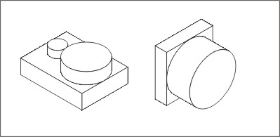
Figure Isometric Blocks and Cylinders
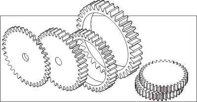
Figure Isometric Gears
Go to Part f Reading a Drawing - Orthographic Projections
Reading Orthographic Projections
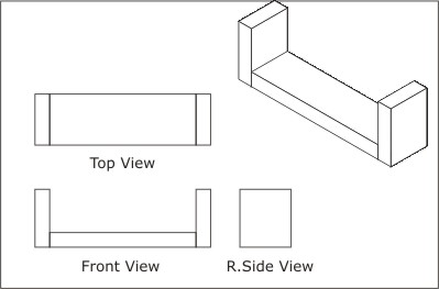
Orthographic projections are projections of an isometric view onto a surface. It should not be surprising then, to learn that the standard orthographic projections are Front View, Right Side View, and Top View. Additional projections may be drawn for complicated isometric drawings. Floor plans for houses and other buildings are nothing more than specially modified top views.
The drawing below illustrates the relationship between an isometric drawing and an orthographic projection.
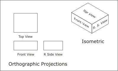
Figure Isometric - Orthographic Relationship
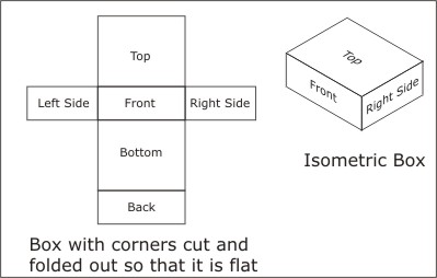
A simple way to to understand the relationship between isometric and orthographic is to cut apart a rectangular box (cardboard, for example) and lay it flat. The next drawings illustrate what happens.
Figure Isometric Box cut and folded flat
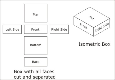
Figure Isometric Box with all faces separated
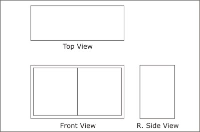
Figure Orthographic Projections
In this figure, the left side, bottom, and back faces have been removed. The top, front and side have been relabelled as Top View, Front View, and Right Side View. Normally these are the only views needed to give enough information to construct the object.
The orthographic drawings below illustrate typical applications of orthographics.
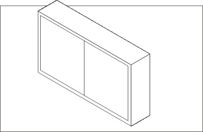
Figure Toolbox without handle
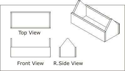
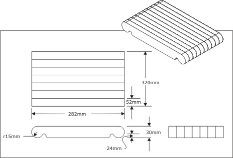
Figure Cutting Board made from laminated strips
Further Information
Check the following site
Activity
Assigned activities
The purpose of these activities is to develop understanding of how technical drawings are made. The activities will give you a feel for the techniques and will help develop your capabilities with sketching and using Corel Draw. All sketches should be done freehand - yes that means no rulers. With a little practice, you can sketch a drawing in a few seconds. Using tools for the same thing can require hours of work. And, using rulers would be defeat the purpose of the exercise. You may wish to practice the drawings a few times to improve your sketching skills.
Technical Drawings using Sketching
- Sketch each of the following drawings using the supplied grid paper. Look at the video clip if you need assistance. There are two sizes. The smaller one is 400 by 300 and will load faster than the larger 640 by 480 size.
- The sketches shown in the videos in this activity are all done with an HB drafting pencil in order for them to show up well in video.
- Normally this would be done with a 2H-3H pencil and, if necessary, darkened with an H pencil.
|
Oblique drawing
|
| 2MB
|
Isometric drawing
|
| 3MB
|
Orthographic drawing
|
| 5.5MB
|
Combined orthographic and isometric drawing
|
|
Test Yourself
There is no self test for this lesson.