
Learning Resources
Lesson
While a network can be very simple, most networks have a few more components. Of course they must all be compatible. That is they must use the same communications protocol. The most common protocol is the internet protocol TCP/IP. Next, they need to use a common physical connection. The most common is Ethernet. Ethernet defines the physical cables, how they connect, and how the electrical signals are transferred over them. All nodes on an Ethernet network can transmit data. Collisions in the data often occur. When that happens, the nodes wait a period of time and retransmit. On a poorly configured network, traffic collisions can significantly slow the network's operation.
Traditional LAN Technologies
Typical components are described below
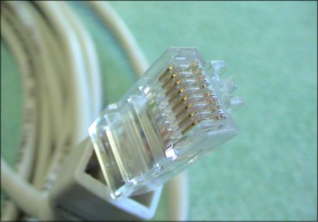
- Ethernet cables. Ethernet cables consist of 8 wires organized into 4 sets of two wires twisted together (twisted pairs). They have an 8 conductor jack on the end called an RJ45 connector similar to, but larger than, a phone jack. Ethernet cables are available in several grades called categories, commonly referred to as Cat.
- Cat 2, for example can be used for alarms, and telephone voice lines.
- Cat 3 can be used for 10 Megabits per second networks (10Mbps) also known as 10BaseT networks.
- Cat 5 is used for fast ethernet (100Mbps) also known as 100baseTx networks
- Cat 5e and Cat 6 are used with gigabit ethernet (1000Mbps) networks
Figure Cat 5 Cable, RJ45 Connector
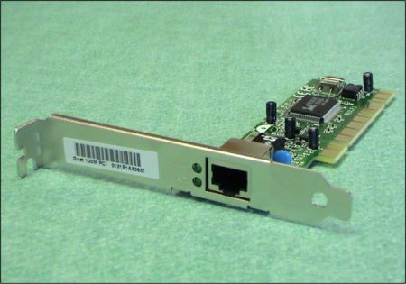
- NIC. The network interface card usually sits in the computer in a PCI slot. It may also be built onto the mainboard. It has an RJ45 socket to plug the cable into. LAN drivers need to be installed before the operating system can address the card and connect to the network. Newer OSs like Windows XP usually have the drivers already installed.
Figure Ethernet NIC. Fits in computer's PCI slot.
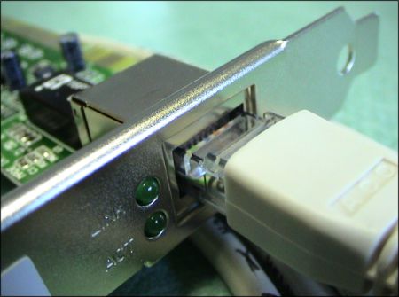
Figure Cat 5 Cable Connected to NIC. If you look closely just to the left of the connector you can see the two status LEDs marked Link and Act (Activity)
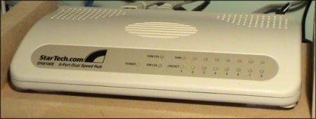
- Hub. A hub is used as the central distribution point in star topology networks. It distributes signals to all the nodes connected to the hub. Every node is sent every signal. The hub does not distinguish one node from another when retransmitting the signals.
Figure 8-Port Hub
Figure 4-Port Hub

- Switch and Routers. These are similar but different devices. A switch looks similar to a hub. It can sit at the distribution point of a star network. It can be used to connect two or more hubs to create a tree network. It functions completely differently than a hub. A switch keeps track of the IP addresses of the nodes on the network. When data is sent to a node, it forwards the data only to the intended node. This reduces the number of data collisions in the ethernet cables, and can improve network data transmission performance by up to 50%. A switch operates on a LAN. A router performs a similar task, but it connects different networks. Routers keep track of the available routes on the networks they are connected to. A router is also a gateway, controlling traffic between two networks.
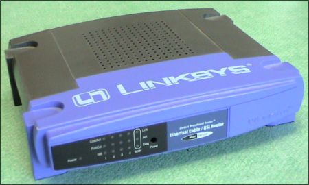
Home and small office networks often use a combination router/switch, often called a Broadband Router. The router part is used to connect the LAN to the WAN (internet). Usually a small LAN uses IP addresses that cannot be seen by the internet, for example 10.0.0.0 (0-255), or 192.168.0.0 (0-255). The router can work with internet addresses on the WAN side of the router, and LAN addresses on the LAN side of the router. It performs what is known as Network Address Translation (NAT). This allows it, for example, to keep track of requests from a browser running on a computer on the LAN, send it out to the internet and when the reply comes back, route it to the correct computer on the LAN.
The switch part is used to manage ethernet traffic on the LAN. Many of these devices have four switch ports, as in the example shown below.
Figure Combination Router/Switch
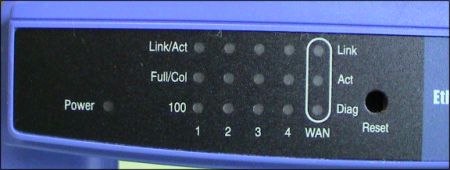
Figure Front Activity Lights.
Note the 4 Switches (1-4), and the WAN indicators. The Switches operate at 100Mbps. The WAN is at 10Mpbs
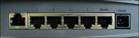
Figure Rear RJ45 Ethernet ports.
WAN connects to the internet through a DSL or Cable Modem. Ports 4 to 1 are 100Mpbs Switch ports. The uplink allows the switch to be connected to another switch.
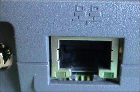
Figure RJ45 Ethernet Port on a Laptop. Note the status LEDs
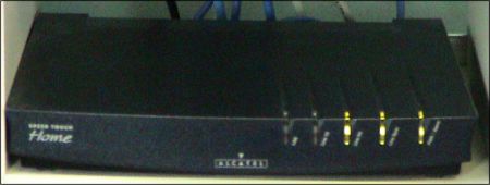
- DSL Modem. Most small-office/home-office (often referred to as SOHO) LANs are connected to the internet through a cable modem or a DSL (ADSL) modem. ADSL stands for Asynchronous Digital Subscriber Line. A cable modem connects to the internet through the cable TV's distribution network. A DSL connects to the internet through the phone companies telephone lines. Both devices are modems (short for modulator-demodulator). They convert computer signals into signals that can be transmitted over coax cable or over telephone wire (modulate), and convert incoming signals into computer signals (demodulate).
Figure DSL Modem
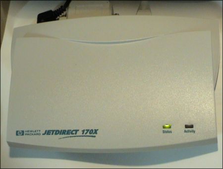
- Printer Server. A printer server is a dedicated device used to connect a printer to the network. This eliminates the need to have a printer attached to a computer. The printer server shown below attaches to the network via an Ethernet connection, and to the printer via a parallel connection.
Figure Print Server
For Additional Information
For more information on networking, check these sites
- How Stuff Works, How Home Networking Works
Activity
Please complete all parts of the activity
- investigate the the school LAN, ort another network
- create a catalogue of all the devices on the network
- create an entry in your course portfolio
- publish the entry to your portfolio website
Test Yourself
There is no self test for this lesson.