
Learning Resources
Lesson
Circuits can be simple or complex. They are essentially arrangements of components, including integrated circuits, which perform one or more functions. A couple of practical examples are illustrated in this lesson.
Series and Parallel
As you saw in lesson 1, a circuit is a complete path for electric current from the source, through the components, and back to the source. Most circuits provide several paths, or loops, for electricity to follow. Each loop has a specific function. Before we look at full circuits, it is useful to look at components in series and parallel, two ways that components may be connected in a circuit and observe the effect on total value of the components.
Series Resistance
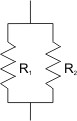
Parallel Resistance
Add all the resistances to get the total resistance.
RT = R1 + R2
For resistances of 30 ohms and 60 ohms,
RT = 30 + 60
RT = 90 ohms
Total resistance is a bit different. You add the inverses.
1/RT = 1/R1 + 1/R2
For the same resistance values,
1/RT = 1/30 +1/60
1/RT = 2/60 + 1/60
1/RT = 3/60
RT = 20 ohms
Series Capacitance
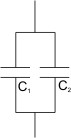
Parallel Capacitance
Total capacitance is found by adding the inverses.
1/CT = 1/C1 + 1/C2
For capacitors with values of 20pF and 30pF, the value is
1/CT = 1/20 + 1/30
1/CT = 3/60 + 2/60
1/CT = 5/60
CT = 12pF
Total capacitance is found by adding all the capacitances
CT = C1 + C2
For capacitors with values of 20pF and 30pF, the value is
CT = 20 + 30
CT = 50pF
Power Supplies
Electronic devices operate on direct current (DC), and at lower voltages. Typical voltages are 12V, 9V, 6V, 5V (a typical value in many computing devices), 4.5V, and 3V (3.3V is used for many computing devices). While battery power can be used for many purposes, it is often desirable to have a power source that plugs into household outlets. That makes it necessary to convert 120V alternating current into one or more of these standard DC voltages. The following diagram illustrates the use of individual electronic components to construct a typical power supply.
Figure Power Supply Circuit
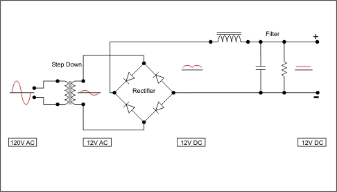
Explanation
- The red indicates the waveform (shape of the current) at each stage of the power supply
- 120 volts AC enters the circuit. AC means that current goes first in one direction and then in the other, as shown by the waveform
- The step down transformer converts 120 volts AC to 12 volts AC. Note that the waveform is only 1/10th as high as the input.
- The rectifier, called a full wave bridge, uses 4 diodes to get the AC pulses to all go in the same direction, as shown by the waveform
- The filter, in this case consisting of an inductor, a capacitor and a resistor, smoothes out the pulses and gives DC similar to what you'd get from a battery, as indicated by the straight line waveform
Amplifier
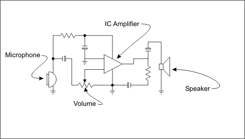
An amplifier takes an incoming signal and boosts it before sending out. A powered megaphone is a good example. The sound is picked up by the microphone, converted from sound waves to electrical signals, amplified, and fed into a speaker located in the 'horn' part of the megaphone.
Figure Megaphone Amplifier
Building Circuits
Historically, electronic circuits have been built a variety of ways. Currently, there are several common methods. Two common ones are
- build it on a 'universal' chassis such as perf board or protoboard,
- build it on a printed circuit board
Perf Board
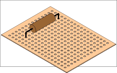
Perf board is short for perforated board. It is a thin plastic material with holes at regular intervals. Holes have copper pads around them to provide something to solder the components to the board. Examples can be see here (click on an image to get more details). Perf board is inexpensive and is often used for prototyping (building a circuit to test it). It is also used to build one of a kind circuits where the cost of creating a printed circuit is not justified. The diagram illustrates how perf board is used. The component is soldered on the bottom.
Figure Perf Board
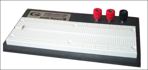
Protoboard
Protoboard is a system that allows components to be plugged into holes. There is a grid of holes, and sets of holes are joined together electrically on the back. Circuits can be prototyped very quickly without soldering, and can just as quickly be disassembled. Protoboards are common in industry.
Figure Protoboard
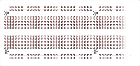
The red and black posts are used to connect to a voltage. If you look closely, you can see a small resistor mounted on the protoboard.
Figure Connections inside the Protoboard
Printed Circuit Boards
When a circuit is to be made permanent, or when circuits are being mass produced, they are mounted on a printed circuit board. A printed circuit board is an epoxy board with copper cladding on one or both sides. It is common to have multilayer boards.
The circuit 'wiring' is created by putting the layout on the copper with an acid resist material, and then etching (dissolving) the unprotected copper. The layout can be applied in several ways
- draw it by hand using acid-resist markers
- print it on using an acid-resist ink on a transfer paper
- apply it photographically using a light-sensitive coating on the copper, which when exposed makes the pattern acid resistant.
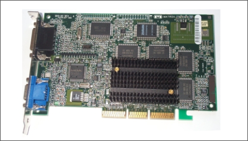
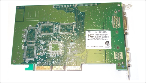
The photographic method provides the most accurate and consistent results. The two photos below show the front and back of a video card circuit board. This complex board has three layers of copper and two layers of epoxy board.
Figure Front and Back of Video Card Circuit Board (Matrox G450 TV)
For More Information
To see more examples of circuits and circuit boards, check these sites
- Kits. This site sells electronics kits. There are many photos of completed circuits on printed circuit boards, and photos of circuit boards with no components mounted on them.
- Protoboard supplier
Activity
The purpose of this activity is to experiment with software that simulates electronic circuits. Several programs are available for this purpose. You will be experimenting with the demo version of Virtual Labs Electricity. The application is available as a free download from
http://www.riverdeep.net/products/downloads/free_downloads.jhtml
Please complete the following. Click View Charges to see how electricity is behaving in the circuits. Click it again to turn it off.
- Take the Tour. This will demonstrate how to use the program
- Work through the SciClopedia. This will illustrate most of the concepts covered in this section of Unit 4
- Experiment with the Labs.
- Open the 4 circuits installed when the program is installed, experiment with them
- Experiment with building series and parallel circuits.
Test Yourself
There is no self test for this lesson.