
Learning Resources
Lesson
The gauges, bells and warning buzzers in the cockpit of an aircraft are the eyes and ears of a pilot. They communicate a myriad of information about the status of the crafts engines, speed, altitude, direction, etc. Computers and sensors on and off the plane constantly update this information. A pilot rarely needs to look out through a window to "see" how the plane is doing. They rely on their instrument panel to "look" for them and help them respond to the outside world.
It is not necessary to focus on the theory of flight to understand how communication occurs on a plane. A good understanding of the instrumentation will illustrate the manner in which human and machine transfer information in order to maintain flight and arrive at a destination.
The cockpit crew is responsible for a large volume of information that is generated by the instrumentation. The layout of the gauges allows a quick scan to track critical information without having to lose sight of any one item. This communication from instrumentation to pilot is critical to the safe operation of the aircraft and affords the pilot the ability to respond in an instant to any parameter of the planes operation.
The 737-400 cockpit panel on the Microsoft® Flight Sim '98 looks like the following:
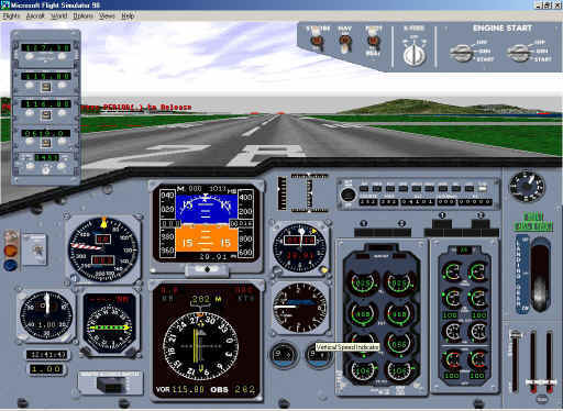
At first glance it is rather a confusing tangle of dials and gauges, but after careful examination it is seen that there is indeed order. The panel is laid out in such a fashion to give a pilot the maximum amount of information possible with one sweeping glance. An expert flyer can read and spot problems in an instant.
Starting from the top left hand corner, proceed around the panel in a counter clockwise fashion. The following is a detailed explanation of the function and information conveyed by each component.
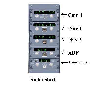
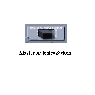
- Radio Stack: The figure below shows the opened Radio Stack. You can open this stack by clicking the Master Avionics Switch located at the bottom of your screen.
The radio stack contains five different areas of importance for the pilot/co-pilot. These are:
- Com 1 - The communications radio which can be tuned to a series of frequencies which access information from the Automated Terminal Information Service (ATIS) which provides updated weather, cloud ceiling, and air pressure information. It also lets the pilot know the current runway in use for takeoff and landings. The Com radio can also be used to speak to the Air Traffic Controller (ATC) who is responsible for directing the planes movements in the air and on the ground.
- NAV1/NAV2 - These are navigation radios that receive signals from ground-based transmitters and coordinate the direction that a plane flies. Setting the radio allows the pilot to pick a pathway to or from an airport along a radial, which is a specialized pathway. The radio can also be tuned to special frequencies that some airports use called ILS or Instrument Landing Systems. These frequencies are used to guide a plane down to a runway. Two frequencies are generated, one called a Localizer and a second called the Glide Slope. The localizer and glide slope antennas are located at the end of the runway and make a path through which a plane can follow to touch down.
- ADF - Automatic Direction Finder. A radio that receives signals from non-directional radio beacons. The pilot can use this beacon to find a relative bearing or direction of the plane.
- Transponder- A special signal generated by tuning the radio to a unique frequency. This frequency is selected by the ATC and identifies the plane with a number on radar screens. The four digit "squawk" code is given to the pilot when clearance for takeoff is requested from ATC.
- Marker Beacon Lights - These lights are displayed when a plane passes the outer, middle, and inner radio beacons on a flight path to a given airport.

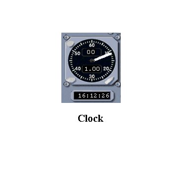
- Clock - Shows the time of day relative to your computer's system clock. It also shows the elapsed time of a simulator session.
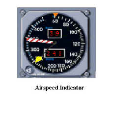
- Airspeed Indicator - The indicated airspeed of an aircraft relative to current temperatures, air pressures, and altitude. The airspeed indicator is not a true reading of the actual speed of the aircraft, rather it is a measure of the forward speed of the plane. The True Air Speed is a measure of the plane relative to the air.
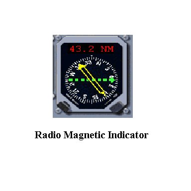
- Radio Magnetic Indicator - This radio receives a signal from an NDB or non directional beacon and gives a magnetic bearing to the beacon. This is used in conjunction with the NAV radios to keep a plane on course. The green needle indicates the direction to the VOR or Very High Frequency Omni Directional Range beacon dialed into the NAV radio and the yellow arrow indicates the direction to the NDB.
- Master Avionics Switch - activates the radio stack on the flight deck panel.
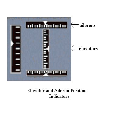
- Elevator and Aileron Indicators - Shows the current position of the ailerons and the elevator which are used to control the roll of the plane (ailerons) and the ascent and descent of the plane (elevator).
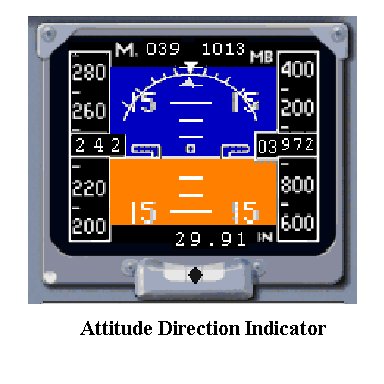
- Attitude Direction Indicator (ADF)- Simultaneously shows the bank and pitch of a plane. The bank of a plane is the angle of roll that it has on an axis through the middle of the plane from front to back. The pitch of the plane is the angle indicated by an axis through the plane from wingtip to wingtip. The instrument is also called an artificial horizon as it gives the planes position relative to the horizon. This instrument cannot indicate whether the plane is following straight and level flight. Three other pieces of information are displayed for the pilot; that of the air speed on the left side of the gauge, the current altitude on the right, and a small black ball called a Turn Coordinator at the bottom which indicates the slip and skid of the plane or whether the plane is falling to the inside or skidding to the outside of a turn radius.
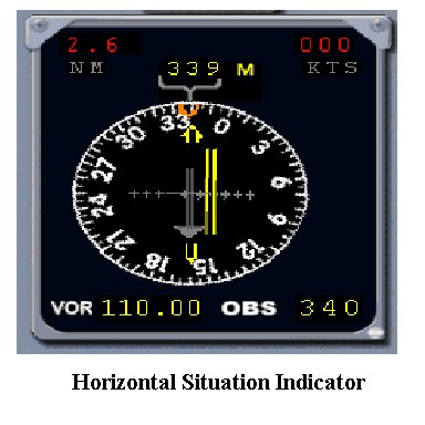
- Horizontal Situation Indicator - This instrument provides a crucial piece of information to a pilot as a course is flown. The instrument is a bird's eye view of your plane as it heads in a direction towards a VOR. The VOR emits a signal which the plane detects by having one of the NAV radios tuned to a particular station. The HSI shows the planes position relative to this signal and allows the pilot to adjust the flight path so as to stay on course. Note the arrow at the center of the HSI. This is called the Course Deviation Indicator or CDI and is an indicator of how far the plane is off course from the VOR.
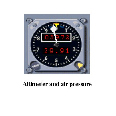
- Altimeter - This instrument gives the current altitude of the plane. It is a sensitive barometer that operates by measuring air pressure and converts the air pressure to feet above Mean Sea Level (MSL). Air pressure decreases as height above sea level increases, but it also varies with the weather. Therefore the altimeter must be calibrated below certain heights and before any takeoff or landing. The pilot receives the current barometric pressure at an airport and dials this into the altimeter to get a current altitude reading. If the altimeter is not adjusted to reflect current barometric pressures the readings may be wrong — perhaps wrong enough to cause a crash.
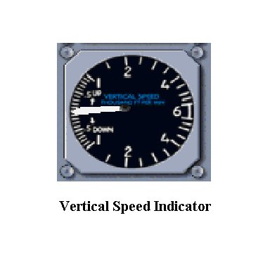
- Vertical Speed Indicator (VSI) - Gives the pilot an indication of how fast vertically the plane is rising or falling. The instrument works on air pressure differences between the inside of the instrument and the outside of the plane. As the plane climbs, the outside pressure decreases and the needle is deflected upwards to indicate climb. The reverse is true of descent.
- Fuel Quantity Gauges - Shows the quantity of fuel in 1000's of pounds in each tank.

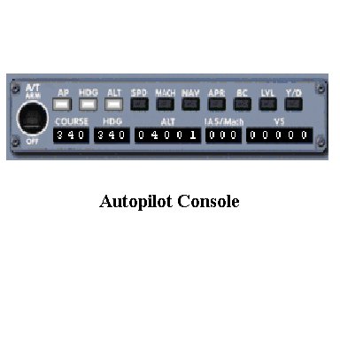
- Autopilot Console - Coordinates the control of the planes onboard systems using computer assistance. The autopilot can, in most cases, coordinate the takeoff from, flight to, and landing at an airport by an aircraft. The pilot generally uses this equipment to generate a more stable flight and to accurately control heading and altitude. The instrument can stabilize movement of the plane in adverse weather conditions giving the travelling public a more enjoyable journey. We will not be using the autopilot.
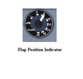
- Flap Position Indicator - Shows the current position of the flaps, a large section on the trailing section of a plane's wings that give more lift or upward movement.
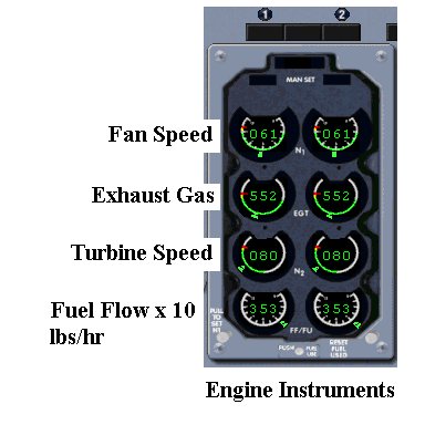
- Engine Instrumentation - A series of gauges and dials that give specific information about the engines, fuel flow, and hydraulics systems of the plane. These are crucial to the pilot in determining the status of operation of the plane during takeoff and landing where engine failure could prove to be catastrophic.
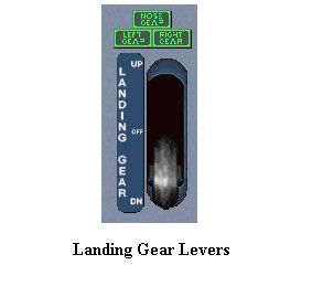
- Landing Gear Levers - Control the opening and closing of the Nose and wing landing gear assemblies. Red and green warning lights indicate whether gear is open or closed and locked into position.
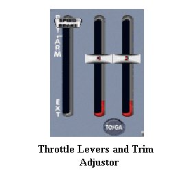
- Throttle Levers and Trim Adjustment - These levers are responsible for the increase and decrease of the engine RPM and thrust. The trim adjustment is used for level flight stabilization after reaching a cruising altitude. The trim adjustment is on the left of the throttle levers.
Activity
Assigned activities
In this activity you will fly the plane, take a 'snapshot' of the plane's instrumentation at a particular place in the flight, and save the image for later use.
- Start the Flight Sim program by double clicking on the icon on your desktop.
- Choose Learn to Fly and then Lessons.
- Select Introductory Flight: Boeing 737-400 as your flight. This is the same flight that you used in activity 1.1.
Important:
- Review the cockpit dials and gauges before you move on to the next stage.
- As in the initial flight, disregard the instructions from the instructor co-pilot
- Complete the following:
- Locate the Flap Position Indicator and press F7, setting the flaps to 15 degrees.
Note that there are five increments of 1, 2, 5, 10 and 15 degrees
- Locate your engine instruments console and press F3, carefully adjusting your power to 90% .
- The Fan Speed indicator (N1) is the top set of gauges. This will give you the required takeoff thrust to lift off the ground.
- When the gauge hits 80% release your brakes by firing the button on your joystick. You should start rolling at this point.
- Use the joystick to keep yourself centered on the runway. Examine your airspeed indicator.
- When ir reaches 145 knots, slowly pull back the joystick and achieve a nose up angle of 15 degrees.
This can be seen on the ADI on your console. The square in the middle of the dial should be centered on the 15 mark.
- Press the joystick button to retract your gear. Press F6 to retract your flaps. Your plane should start to pick up air speed.
- When ir reaches 145 knots, slowly pull back the joystick and achieve a nose up angle of 15 degrees.
- Climb until your altimeter reaches 3500 ft and then ease your stick forward to level your plane.
- Try to level off at about 4000 ft.
- Press your F2 button and reduce your power to 55%.
- Locate the Flap Position Indicator and press F7, setting the flaps to 15 degrees.
- Take a snapshot of the panel and save it
- Take a screen shot of your panel by pressing Alt-PrtSc together.
- Minimize the screen and start CorelDraw 10 or Paint.
- Once inside the program, click edit->paste.
- Resize the resulting screen shot and save it with the filename 12level.bmp
Test Yourself
- Give your explanation of why the HSI, ADI, altimeter, airspeed indicator, and vertical speed indicator are grouped together.
- Given the definition of communication you learned in Unit 1, how does the console of the plane fit this definition?