| Intermediate Technology Education | Control Technology | Design Stage 2 | Topic 6 | Knowledge/Skill Activity 1 |
Understanding Technical Drawings
- Identify what makes a drawing a technical drawing
- Identify types of technical drawings
- Identify uses of technical drawings
What are Technical Drawings
Technical drawings are line drawings made according to a set of rules and procedures. The rules and procedures are pretty much standardized throughout the world. Types of lines, how they are placed and where different parts of the drawing are placed enable anyone to read and interpret the drawing and reach the same decisions. In fact, technical drawings are a universal language for communicating technical information.
Types of Technical Drawings
While there are many types of drawings, and even many types of technical drawings, we are concerned here with two general types of technical drawings
- Isometric, or pictorial drawings, which represent an object in a three dimensional fashion by showing 3 surfaces of the object in one drawing.
- Orthographic, or plan view drawings, which represent an object in a two dimensional fashion by showing each surface of the object in its actual shape.
Pictorial Drawings
Pictorials are picture drawings that show more than one side of an object at the same time. The most common forms of pictorial drawings are
- Perspective. This is the most accurate, but the most complex to draw. It tries to replicate what we actually see. Photographs are naturally 'perspective). It requires complex setups with mechanical drawing tools, or special versions of CAD software to do. Sketching this technique requires skill.
- Cabinet. This is an older style that is used to approximate one-point perspective using vertical, horizontal, and lines at one other angel (either 30 or 45 degrees but never both).
- Isometric. This is a more recent style that uses vertical lines and lines at 30 degrees. It is used to approximate two-point perspective It can be done easily by sketching, or with mechanical drawing tools. Many CAD tools support the format directly. This is by far the most commonly used technique.
The following sequence of images illustrates the relationship of one-point perspective to cabinet projections.
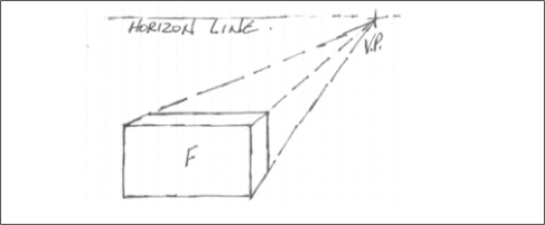
Figure 1-Point Perspective
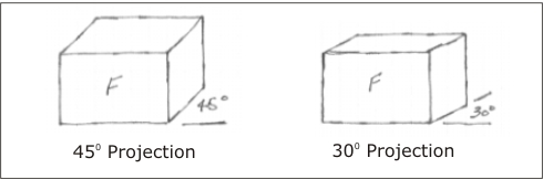
Figure Cabinet Projections as an approximation of 1-point
perspective
The next sequence illustrates the relationship of isometric drawings to two-point perspective.
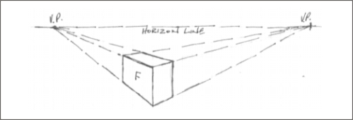
Figure 2-Point Perspective
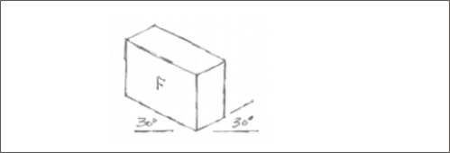
Figure Isometric Drawing as an approximation of 2 point
perspective
Isometric drawings are unique in that the edges are drawn vertically or at 30 degrees to the horizontal. As well, isometric drawings generally only use one type of line—a thin solid line—and do not use colour or shading. The image below illustrates that clearly.
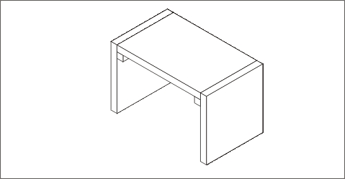
Figure Isometric Drawing of a Stool
Pictorials are drawn when you want to show what something looks like. Here are a few more examples of isometric drawings.
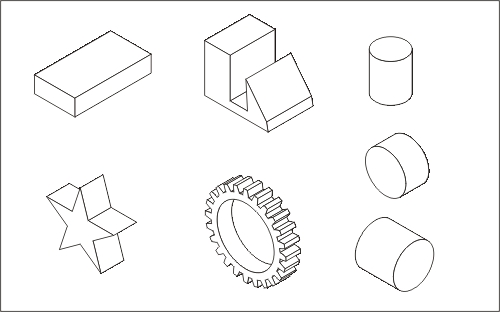
Figure Sample Isometric Drawings
The example below breaks one of the rules for isometric drawings. How does it break the rules?
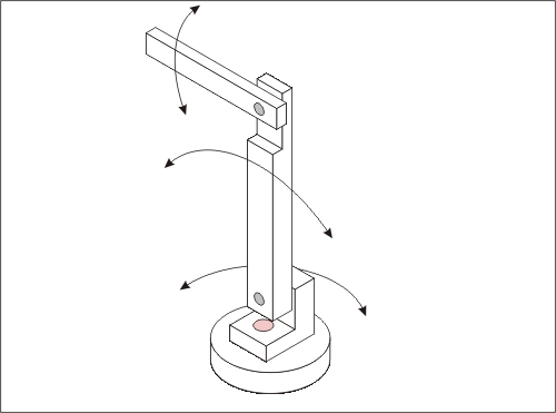
Figure Isometric Drawing of a Robot Arm
You may wish to try this interactive isometric drawing tool. It will let you construct simple shapes. It does illustrate the typical grid structure of isometrics.
Orthographic Drawings
Orthographic drawings are related to isometric drawings. Isometrics show multiple sides of an object at the same time. Orthographics show individual views of the objects. The next sequence of drawings shows how that relationship works, beginning with labeling of the sides of an object in isometric drawings.
We start with a box, shown as an isometric, and them we label its surfaces. Like all boxes, it has 2 ends, 2 sides, and a top and bottom.
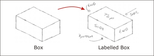
Figure Isometric Drawing of Box with Labels
The labels we used are descriptive, but they don't tell us much about their location on the drawing. The next drawing shows what we call a convention. Over time, people on the industry agreed that the labels used in the next drawing would be the accepted ones. That is, regardless of what was in the drawing, the labels would always be the ones in the drawing.
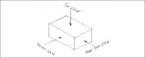
Figure Properly labeled Isometric Drawing
The next drawing shows how the labels are used, regardless of what is in the drawing. You may argue that it does not make sense to call the front of the truck, the Right Side View, and the side of the truck the Front View. The answer is , "we are not". We are labeling the location, not the object. It is very important to keep this in mind.
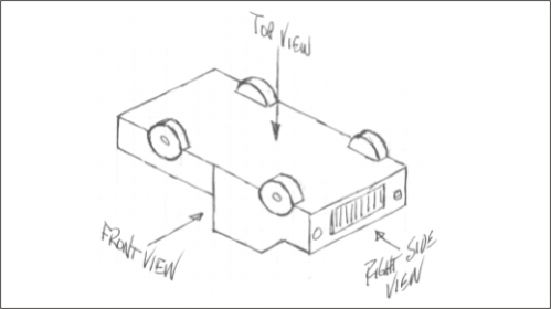
Figure Use of Proper Labels
You may be wondering about the three views that are hidden. They are called the Bottom View, the Left Side View, and the Rear View. Can you determine where they go?
The next drawing shows the relationship of isometric surfaces to the views in orthographic drawings.
- Look at image 1. It is an isometric box with labels.
- Image 2 shows what the box would look like if we cut it along the edges and made it flat. Pay attention to the surfaces. Note where the Top, Front and R.S. Views appeared in drawing 2.
- Image 3 shows the same flattened box with the Rear, L.S., and Bottom views removed. Since they are identical to the remaining 3 we usually don't need them.
- Image 4 shows the remaining 3 views, separated so that we can focus on each one independently. Image 4 is typical of what we refer to as an orthographic drawing (or projection).
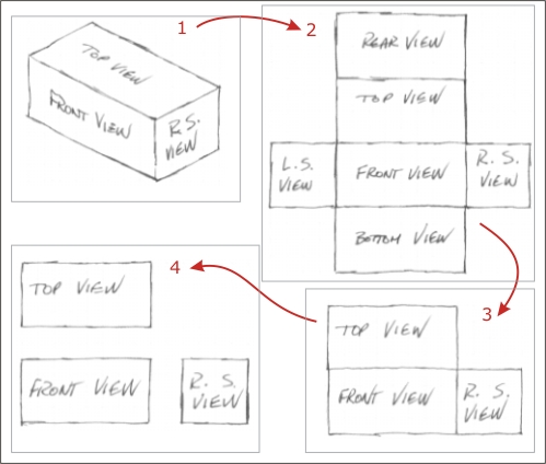
Figure Relationship of Isometric to Orthographics
The more sophisticated explanation for this relationship focuses on the views as projections of the surfaces. If you have interest in further exploration of this subject, you may wish to check the page Isometric Drawing and Third Angle Projection.
Remember that upside down truck in the isometric above? Here is what it looks like as an orthographic drawing.
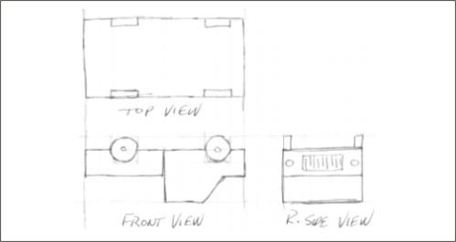
Figure Orthographic Drawings of the Truck
Now that you know the relationship between the isometric drawing and the orthographic views of the same object, it may com as no surprise that there how you orient the object in an isometric drawing affects the physical space needed to make the orthographic drawings. The next set of drawings shows the same box, but placed in different directions. Drawing 1 on the left has the long direction along the front view, resulting in a compact drawing for the Orthographics. Drawing 2, on the right, has the long direction along the right side, resulting in a taller set of orthographic drawings. Placing the long direction along the front view is another convention when creating isometric and orthographic drawings.
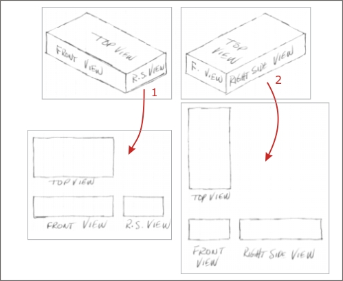
Figure Drawing 1 is the conventional way to position an Object
The next figure shows the convention for technical drawings, when both the Orthographics and Isometrics are on the same sheet. This type of orthographic is called Third Angle Projection, and is widely used in North America. Another type called First Angle Projection is more common in Europe.

Figure Orthographics and Isometrics placement.
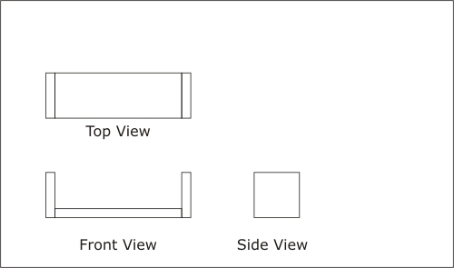
As you can see in the next figure, the use of both types of drawing can contribute to understanding what the drawings are describing.
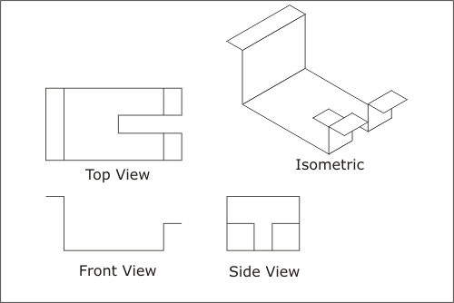
Figure Sheet Metal Shape
The placement of each drawing in an orthographic has special meaning. The next drawing has labels for each of the drawings. Each drawing is a single view of the object. Views are always placed in the locations shown.
Figure Orthographic Views of an Object
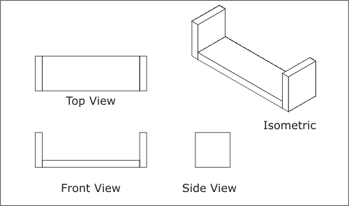
Note that regardless of the object, the views are labelled exactly as shown. The next image shows how the views relate to an isometric drawing of the same thing.
Figure Relationship of Views and Isometric Drawings
Sometimes both types of technical drawing are needed to understand an object's structure, as in the next example.
Figure Sheet Metal Clip Drawings

For More Information
If you wish more information, check these web pages
When you are ready, go to Your Turn