| Intermediate Technology Education | Energy and Power Technology | Design Stage 2 | Topic 6 | Optional Activity 7 |

Solar Construction Challenge

Tracking the Sun

For this activity you will need:

  • Empty CD / DVD Spool
  • Gear motor (modified servo)
  • Large plastic wheel for the gear motor (2 would be better)
  • Friction band or #61 elastic band
  • 2 Solar batteries (one will do if you don't have 2)
  • Miscellaneous stuff - double sided tape, elastic bands, wood block, metal or plastic strips (read the activity)
  • Philips screwdriver

Modify the CD Spool

In this activity the CD spool will act as the turntable to rotate the solar panel.

  • Start by cutting the 3 locks that keep the cover attached to the base. Use cutters and a file or sharp knife (careful). Make sure you don't damage the extended edge of the base. The cover will have to rotate on this surface.

Figure. CD spool showing cover locks

  • Next, make a small hole in the base using a drill bit, a sharp knife or, one blade of a scissors. Be careful and don't use a folding pocket knife! The hole should be about the diameter of a pencil. See the next illustration for the hole placement.

Figure. CD spool base with cover locks cut off

Modify the Gear Motor

The gear motor will be used to rotate the cover of the CD spool. It will fit inside provided a few modifications are done.

  • First, the two wire leads must be moved to the other side so they won't interfere with the rotation of the cover. Start by taking out the 4 screws that secure the bottom of the motor. Those screws also keep the top on. You might put some tape over the motor top so it won't fall off and spill the gears!

Figure. Gear motor with bottom removed and tape on top

  • Bend the wires back to the opposite side and put the bottom back on. Make sure you have the strain relief on correctly (the black rubber piece that holds the wires in place. When you are sure it's in the right place, put the screws back in.

Figure. Wire routed to opposite end

  • Finally, you have to cut off one of the mounting tabs. Hopefully you won't need this in the future. Cut off the tab closest to the output shaft (furthest from the motor). The plastic is very hard, use a cutter and file or trim the plastic until it is smooth.

Figure. Modified motor with tab cut off

Mount the Drive Wheel

To provide friction, a rubber band must be placed around the large servo wheel. In the illustration below, a friction band used on the large drive wheels from the Intermediate Control module is used but a #61 elastic band will do as well. If you have access to 2 servo wheels you can put them back to back which will give a better edge for the band.

Figure. Servo wheels and friction bands

  • Mount the band on the wheel(s) and screw on to the gear motor using the appropriate screw,

Figure. Servo wheel and friction band

Mount the Gear Motor Assembly

You need to mount the gear motor with drive wheel on the CD spool base.

  • Use a square of double sided foam tape and place it near the front of the motor (the end with the cut off tab) closest to the rim of the CD spool base. Carefully line the motor up with the center post of the CD spool. Make sure the mounting tab is snug against the post before you press the tape down.

Figure. CD base with gear motor mounted with double sided tape

Once engaged, the motor may tend to rise up on the foam tape. The motor can be further stabilized by twisting an elastic band around the center post several times and pulling it down so it keeps the motor mounting tab tight against the center post.

Figure. Gear motor secured to post with elastic band

Test the Drive Motor

  • Turn the CD spool cover upside down. Carefully fit the spool base and motor assembly down ito the cover making sure the center post engages the hole in the cover. Don't press the base down tightly! Just make sure the center post is in the cover hole.
  • Connect the motor wires to a solar battery and just lay it flat on the CD spool base. It doesn't matter which way the wires are connected, we will adjust that later. Bring an incandescent lamp near the base and, if you have it right, the base should start to rotate as the motor rotates.

Drive Motor Test

Video. Drive Motor Test

Mounting the Motor Drive Solar Battery

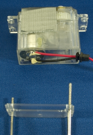
If your test was successful, you need to mount the solar battery 
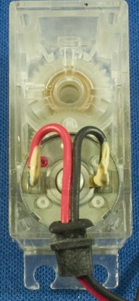
perpendicular to the CD spool base. You also need to be sure the motor lead wires are connected to the correct solar battery terminals.

  • Mount the solar battery and connect the leads

The video from Step 6 shows the spool base rotating in a counter-clockwise direction (as seen from above). This would be find fine if you lived in Australia but in the Northern Hemisphere it has to rotate clockwise (again, as seen from above).

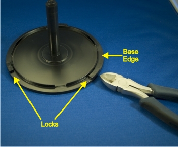
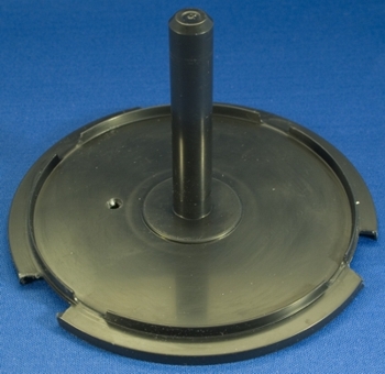
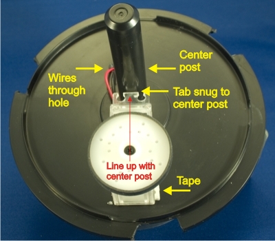
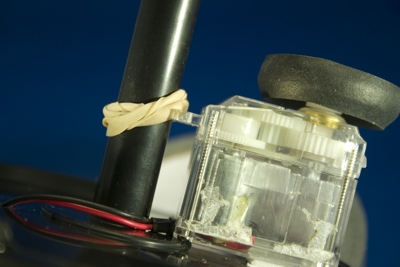
  • Use  small block of wood and some double sided tape to mount the drive solar battery at 90 degrees to the spool base. Make sure the block is not in the center of the base.

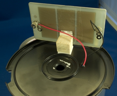
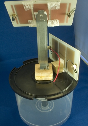
Figure. Solar array to power drive motor mounted on CD base

The idea here is that the solar battery will cause the base to rotate when it (the solar battery) is facing the sun. As the base rotates the solar battery will no longer face the sun and the motor will stop.

  • Test this by placing the spool with the solar battery facing an incandescent light.

 Tracking Test

Video. Tracking Test

Mounting the Primary Solar Array

Of course the main function of a sun tracking device is to keep a solar array facing the "moving" sun.

  • Mount a second solar battery or other solar cell array on the base so that it is directly facing the light when the base stops rotating. Here's an example of how to mount the second array.

Figure. Solar array for energy output mounted on base

A "slot cover" from an old computer is mounted on a wood block with a wood screw. The wood block, cut to just fit the spool's center area, is attached with doubled sided tape. Using a pliers, the upper section of the metal cover was bent to an angle which approximates the sun's angle (maybe around midday). The array was attached with tape.

  • Use a similar method to mount your solar array.
  • Position the array so that when the CD spool base stops moving (see step 8) it is exactly facing the light. On a sunny day you can take the apparatus outside and see if it works in the sun. Indoors you can move a light slowly around the array to test the tracking function. See the next video for a demonstration.

Demonstration

Video. Demonstration

Going Further

If you wish to expand on this knowledge/skill building activity as the basis for a design activity, consider the following.

  • What can the primary solar array be used for?
  • When the sun goes down the solar tracker should return to the East to wait for the rising sun.
  • The sun doesn't follow a straight path across the sky. The primary array will exactly face the sun for a short time each day depending on the bend in the slot cover. The primary array needs to be able to change its elevation.