| Intermediate Technology Education | Energy and Power Technology | Design Stage 2 | Topic 6 | Optional Activity 2 |

Wind Energy Applications

Using Wind Energy

In this activity you will need the following:

  • Wind generator from Activity 4
  • Electric Fan
  • Clamp or lab stand with test tube clamp
  • Alligator clip leads
  • LED with resistor
  • Gear Motor with thread spool
  • Selection of Weights
  • USB Oscilloscope (optional)

Connecting the LED

Set up the DC generator as in the last Activity with the appropriate clamps and stand. Use the motor - propeller combination that gave the best voltage. Place the fan in the same proximity to the propeller.

This time, connect the two alligator leads to the generator and to the leads of an LED from your kit. Caution, the LED must have a resistor in series with one of its leads. Do not use an LED that does not have a current limiting resistor attached.

LEDs are diodes and only allow current to pass in one direction. Since the wind generator's electrical output is DC it does matter how this component is connected.

On a LED without the resistor, the short leg is called the cathode or negative lead. If there is a resistor attached, you can tell the negative lead as it is next to the flat side of the rim that is found at the base of the LED.

Figure. LED lead information

Figure. Block diagram of LED and resistor connected to generator

Lighting the LED

Put on your safety glasses and start the fan. When the propeller comes up to speed, check the LED. If it doesn't light, reverse the leads from the generator.

If you have more LEDs with resistors, connect them (in parallel) with the LED currently in the circuit. Does your generator have enough energy to light them? Does the propeller slow down as more LEDs are connected? Why?

Lifting a Weight Using the Wind

In the last activity, you identified which generators gave the best current and voltage. A way of demonstrating which combination produces the most energy is to use the output to lift a weight. The heaviest weight lifted gives an indication of the energy of the system.

Connect the motor / propeller combination that gave the best voltage to the gear motor which has the thread spool attached. Use alligator clips. If you don't have a thread spool attached to the gear motor, click the next link for some instructions.

Thread Spool

Attach the gear motor to the table top with the spool out over the edge. Attach a small mass to the string (~100 grams) and place it on the floor. Leave the string slack so the gear motor can start before it has to lift the weight.

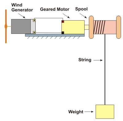
Figure. Diagram of generator and gear motor winch

To see a video clip showing the setup, click the next link.

Video Clip

Put on your safety glasses. Start the fan.

If the gear motor lifts the mass. Reset the string length and add another mass to increase the total. If the gear motor does not lift the mass, use a smaller one of 25 or 50 grams.

  • What was largest mass lifted?
  • Can you calculate the power developed by the gear motor (Hint: Power = work / time)? 

Repeat the Lift (Optional)

If you have time, you could try more motor - propeller combinations.

Which delivered more energy?

Look at the Generated Voltage

If you have access to the DS1M12 PC Oscilloscope, connect channel A to your generator using the supplied probes.

Run the software and set the following on the EasyScope software:

  • Channel A
  • TimeBase 100 ms
  • Volts/Div 2.0 volts
  • Trigger Auto

When you are ready, put on your safety glasses and start the fan. Click the Run button and when you have a trace, click stop.

Save the trace as a file (bmp) for your report.

Comment on the type of electricity generated.

How does it compare to the "ideal" trace for that type of electricity?