| Intermediate Technology Education | Control Technology | Pre-Design | Topic 3 | Activity 7 |
Electrical Systems
- Review the basics of electricity
- Review the components of an electrical system
Electricity
Electricity is a form of energy produced by the movement of electrons. Electrons are subatomic particles that have a charge, which we describe as a negative charge. They are attracted by other subatomic particles, called protons, which have the opposite, or positive, charge. Electrons repel each other. It is these forces of attraction/repulsion that cause electrons to flow through conductors.
Some types of atoms allow electrons to move from one atom to another, under certain conditions. Materials with this type of atom are called conductors. Other types of materials never allow electrons to flow from one atom to another. We call these types of materials insulators.
There is another type of material called semiconductors. This is material that has been designed to allow electrons to flow under certain conditions, but not under other conditions. The conditions that enable or disable electron flow can be controlled, sometimes by the user of the device.
For electrons to flow from one location to another, there must be an excess of electrons in one location and a shortage of electrons in the other location. This difference is sometimes called potential difference, or electromotive force (abbreviated to EMF). We can artificially generate EMF by converting another form of energy into electrical energy. Common methods are chemically (batteries), and magnetically (turbines rotated by nuclear, wind, water, or other energy source).
Regardless of method of creation, to do useful things with electricity, an electrical circuit is required. An electrical circuit always needs at least 3 things—a source of electrical energy, conductors to carry the electrons, and a load, or something to convert the electrical energy into useful work. In its simplest form, a circuit is represented in the figure below. It has a source of EMF, conductors, and a load.
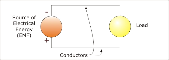
Figure Basic Electrical Circuit
You may have noticed that this circuit is missing something. There is no way to turn it on or off. It has no form of control mechanism. The next figure adds control, in the form of an on-off switch, to the circuit. It is the basic form of an electrical control circuit.
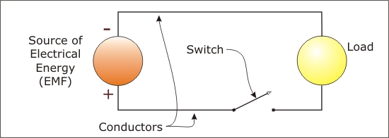
Figure Basic Electrical Control Circuit
For the types of electrical circuits you will be using in this module, the source will be a battery or a plug-in transformer type of DC power supply. The load will typically be a light bulb, a Light Emitting Diode (LED), or a small electric motor. The switch can be a small toggle, a joystick control that comes with the small tractor kit, or the Phidgets interface that is controlled by a computer (see next activity).
To work with these devices in small electric circuits, a few more bits of electrical theory and terminology are important.
Electrical Circuit Components and Symbols
We use simplified drawings called schematics to show electrical circuits. Each device in the circuit is represented by a symbol. Each device has its own symbol. Symbols of most of the devices used in this module are shown below
| Symbol | Description |
|
|
Single electrical cell, for example an AA or AAA cell. A single electrical cell typically has an EMF of 1.5 Volt (Volt is the unit of measure for EMF). Electrical cells produce direct current electricity. Electrons always flow around the circuit in the same direction. |
|
|
Electrical Battery. A battery is made from two or more cells. A 3 Volt battery has 2 cells. A 9 Volt battery has 6 cells. This symbol is also used to denote any direct current power supply, such as a plug in power supply for a small electronic device. |
|
|
Incandescent light bulb. This is a regular light bulb that resists the flow of electrons. Its resistance generates heat and the heat makes the filament get hot enough to give off light. |
|
|
Light Emitting Diode (LED). This is a semiconductor device. It allows electrons to flow through the device in one direction (direction of the big arrow), and this causes it to give off light. It does not generate much heat. It does not allow electrons to flow in the reverse direction, hence the name semiconductor. Because of this, it is important to maintain polarity (+ or -) when connecting it. |
|
|
Resistor. Resistors are elements
used in a circuit that impede the flow of electrons. It does this by
converting some of the electrical energy into heat. As stand alone
devices, resistors are used in many electronic circuits. Even LEDs
need a small resistor attached to them to prevent them from using
too much electricity and destroying themselves.
In addition many devices in our houses are essentially large resistors—the electric stove, electric heat, electric kettles. |
|
|
SPST switch. Single pole, single throw. Essentially and on-off switch |
|
|
SPDT switch. Single pole, double throw. A switch that can turn on one circuit while it turns off another. One circuit is always on and the other is always off |
|
|
SPDT, center-off switch. This is a switch with three positions. In the center position, neither circuit is energized. Moving to either side energizes that circuit. any one of the circuits can be on, or both can be off. |
|
|
Ground. In direct current circuits, this is often used to designate the negative connection, especially if the drawing is complex. |
|
|
Electric Motor. A device that converts electrical energy into rotary motion. A DC motor can be reversed simply by reversing the electrical connection. |
Electrical System
An electrical system is a complete electrical circuit that is designed to perform a specific function. The circuits illustrated below are of simple electrical systems.
Simple Electrical System—Light Circuit
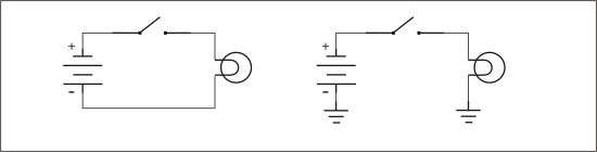
Figure Light Circuit. Two versions of the schematic
The video clip shows the light circuit in action.
Video Light Circuit
Simple Electrical System—Motor Circuit
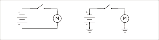
Figure Motor Circuit
The video clip shows two versions of the motor in action.
Video Motor Circuit
For More Information
For more information on the topics above, check these web sites
- Howstuffworks How Electricity Works
- Circuit Symbols and Circuit Diagrams (and other pages at this site)
- Circuit Schematic Symbols
- Circuit Symbols of Electronic Components