| Intermediate Technology Education | Control Technology | Pre-Design | Topic 3 | Activity 5 |
Pneumatic Systems
- review basic principles of compressed air
- review basic applications for compressed air
Pneumatics Principles
Pneumatics is the application of compressed gasses (usually air) to do work. Compressed air is air that has a higher pressure than the atmosphere. Air pressure is increased by putting more of it into the same volume, for example by using a bicycle pump to put air into a bicycle tire. The basic principles of compressing air are illustrated in this video clip
Video Compressing Air
Air, like other gases expands to fill the space it is in. When air is compressed in a closed container, the air pressure is the same everywhere in the container. That is why air-filled tires can carry bicycles and trucks. The relationship between pressure and volume of a gas is known as Boyles law. Robert Boyle made the discovery in 1662 after it became possible to pressurize gases. Essentially, Boyle's Law says that if you decrease the volume of a gas (put it in a smaller space), the pressure will increase. Of course the reverse is also true.
Pneumatics, then is the application of Boyle's (and other) Law's to do work. When working with gases, you also have to take into account things like temperature changes and the type of gas, but for this activity those things are not relevant.
As stated above, the purpose of compressing air is to use it to do useful things. The next two video clips illustrate the basic principles of using pneumatic cylinders to create motion. The two cylinders are connected directly together with plastic tubing. The cylinder which is being manipulated directly is the source of power in the pneumatic system. The cylinder which is being acted on by the air pressure is the driven, or work cylinder. The relative volumes of each determines the mechanical advantage.

Video Basic Pneumatics Video Pneumatic Arm
After looking at the following video clips, identify the inputs, processes
and outputs for each pneumatic system. What kind of motion is created for
each device?
Video Pneumatic Nailer Video Pneumatic Nibbler
Video Pneumatic Punch/Flanger
Compressed Air Applications
Compressed air applications make use of pneumatic actuators. Actuators use the energy stored in compressed air to create motion. Motion can be linear or rotary.
Linear actuators typically use some sort of cylinder, which can be single acting or double acting. In the next two drawings, the force acting on the cylinder is air pressure.
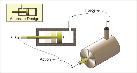
Figure Single-acting Cylinder
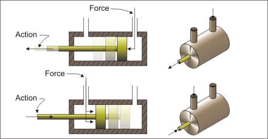
Figure Double-acting Cylinder
Sometimes a single acting cylinder has a spring to pull or push it back after the air pressure is released. This effectively makes it double-acting. The puncher/flanger tool in the video above is just such a mechanism.
Pneumatic linear actuators are used for a variety of applications, including
- Truck brakes
- Pneumatic tools
- Clamping devices
- Positioning devices
By connecting the end of the piston rod to a rotary device, rotary action can be created from linear action. The next illustration shows the basic principle. Air into the right input causes the piston to move left, and air into the left input causes the piston to move right. Can this device be modified to make an air compressor?
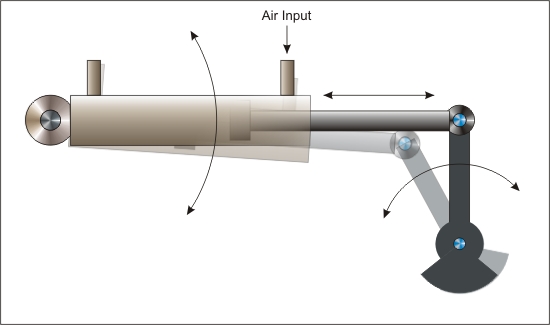
Figure Pneumatic Linear Actuator to Rotary Conversion
Rotary motion can be created directly from compressed air. The compressed air blows across a set of blades or vanes, causing the 'motor' to spin. The next illustration shows the principle. Actual devices will have blades that have a different shape to improve power conversion. Can this device be modified to make an air compressor?
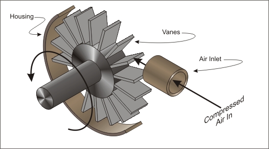
Figure Rotary Actuator Powered by Compressed Air
Pneumatic rotary actuators are used as compressed air motors in a variety of devices, including industrial drills, sanders, screwdrivers and nutdrivers, and dentist drills.
Pneumatic Systems
As with all systems, pneumatic systems have inputs, outputs, and feedback/control mechanisms. Most handheld pneumatic tools (systems) rely on the operator for feedback (observation) and control (start/stop/speed adjustments).

Figure Open System for Small Hand-held Pneumatic Tools
The following video illustrates the combination of different systems—electrical, mechanical, and pneumatic.
- The electric system employs a power supply and a small DC motor.
- The mechanical system employs a small worm gear on the motor shaft, coupled to a larger gear. the larger gear uses an off center pin which is connected to the shaft of a Lego pneumatic piston to convert rotary motion into linear motion.
- The pneumatic system converts the linear motion from the mechanical system into compressed air. The Lego piston acts as an air pump. It uses an internal valve to ally air to move in only one direction. It is connected by a tube to a second piston. As the pump compresses the air, the second piston is forced to move. Later in the video, manual control is added by using a 3 way valve to change direction of force from the compressed air. The driven piston is a two way piston, so by moving the contrl lever, the direction of motion in the driven piston can be changed.
Video Pneumatic Pump with Manual Control
For More Information
- Pneumatics
- Principles of Fluid Power
- Pneumatics - Wikipedia, the free encyclopedia
- FPEF - Advancing & Supporting Fluid Power Education
- Air-Driven Diaphragm Pump How It Works PumpStoreUSA.com
- Pump Types Menu - Engineers Edge
When you are ready, go to Your Turn