| Intermediate Technology Education | Control Technology | Design Stage 3 | Topic 1 | Knowledge/Skill Activity 3 |
Control Systems
- Examine control components and systems
- Plan fabrication sequences that include control components and systems
Control
As you learned in an earlier activity, control is about 3 things
- Sensing, which can measure, or determine
- if something exists (for example, the presence or absence of light, electricity, pressure, etc.) example
- changes in a process continuously over time (for example, changes in light intensity, electrical voltage or current, or air pressure. measured at regular intervals over a period of time)
- Switching something on or off (for example turning a motor on or off)
- Regulating a process continuously over time (for example changing the speed of a motor)
Control Systems
Control systems are made up of several subsystems
- A structural system. This is the framework, the chassis, and other parts that comprise the physical structure of the system.
- A source of energy. This is what powers the system and enables it to perform the specified tasks
- A control system. This is the mechanism that determines how and when the systems performs its tasks.
Lets take an overview look at each of the following types of control system which have been illustrated by examples in this module
- Mechanical
- Pneumatic
- Hydraulic
- Electrical/Electronic
- Computer managed
Mechanical
Mechanical systems consist of the framework and structure of the system, especially those moving parts of the physical structure like arms, levers, gears, pulleys, cams and drive belts. The focus in this module's demonstrations has been on mechanical systems as part of other systems. Almost any system that is powered by pneumatics, hydraulics, electric motors and so on will also be built around mechanical structures.
For a look at purely mechanical systems check these web pages.
- Design and Technology Check projects 4, 5, 6, and 7
- Mechanisms
- Mechanisms and Movement
- Mechanisms
If you want to experiment with design and testing of truss structures, try the West Point Bridge Designer. You will need to download and install the software. A number of versions are listed, one from each year of the competition
The tool may be helpful in designing a trussed structure for a platform or a crane, for example.
Pneumatic
Pneumatic systems use a compressed gas as the source of power. Most systems use compressed air. Compressed air systems can be complex and sophisticated with a variety of control mechanisms. Typically control is accomplished with control valves which can route compressed air to one or more different devices at the same time.
Control of a compressed air system takes the following forms
- Opening a valve to allow compressed air into the system
- Regulating the amount of time that the valve is open (how long the pressure is applied)
- Regulating the pressure of the air.
These forms of control in pneumatic systems can be used to
- Create linear motion by forcing a piston to move. Applying air pressure to one side of the piston moves it in one direction, and applying it to the opposite side moves it in the other direction.
- Create rotary motion by passing the air over a set of blades. To reverse the direction, the air has to blow over the vanes in the opposite direction.
Examples of pneumatic systems used in this module are very simple ones. The energy source is a cylinder that has to be pushed by hand to compress the air. The system is closed and air does not escape, so you can push the piston to do work and then pull back on the piston to do work in the opposite direction. You can see this action in several of the demonstration video clips. This cylinder is also the control device—you push and the other cylinders move, you pull and the other cylinders move. Do you know why it works in both directions?
In the example below, the control device is a pneumatic cylinder and it is exactly the same size as the other two cylinders. It is also the power source, since it operates the other two cylinders. Notice the use of a manifold to send the air from one cylinder to two cylinders. The three cylinders are exactly the same size. When the piston is moved in the control cylinder, each piston in the other two cylinders moves exactly half the distance the control plunger moved. Can you figure out why?
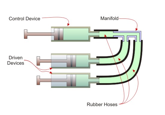
Figure Pneumatic System
You may wish to look at the pneumatics examples on this web site
Hydraulic
Hydraulic systems use a liquid under pressure as the source of power. Since the liquid cannot compress, the system can exert a lot of power. As well, it is more precise in its movements than a pneumatic system. The examples used in this module employ the same cylinders as were used for pneumatics, and are subject to the same limits in terms of how they are controlled. The information on pneumatic control outlined above applies to hydraulic control as well.
Real-world hydraulic control systems are subjected to much higher pressures than pneumatic systems and as a result use different cylinders, different control mechanisms and a different method to pressurize the liquid. While some of the components may look similar to those in pneumatic systems, they are constructed from stronger materials. In addition, the physical structures that hydraulic systems are attached to are much stronger.
Electrical
Electrical systems use electricity as the source of power. The work gets done by a light bulb, a motor, a heater, a stove top element. The electrical energy gets converted to heat energy. In the case of the light bulb, the heat is intense enough to make the element give off significant amounts of visible light. Other types of lights, for example fluorescent and LED, each work differently to convert electrical energy into light. In all cases control consists of devices which can manage the flow of electricity through the device.
Electrical control can
- Turn the electricity on or off
- Regulate the amount of electrical current (number of electrons) that can flow through the device
- In the case of direct current (DC) control the direction of electron flow. DC current direction can be used to control motor spin direction in DC motors, for example.
The electrical control devices used in the examples in this module were simple on/off switches (SPST), and H-Bridges (switches that can also change the current direction through the electrical device).
Electrical systems can be combined with pneumatic and hydraulic systems. Hydraulic actuator valves (valves the start, stop, and regulate the flow of hydraulic fluid), can be manipulated electrically. A solenoid (electromagnet) can be used to open and close the actuator for example.
The following pages provide information on basic electrical control devices, as well as electronic devices.
Computer Control
Computer control can be substituted as the control system in any other system. It can sense, switch, and regulate any physical process including mechanical, pneumatic, hydraulic, and electrical. And it can be used to control very complex systems with all the above. Consider that the most complex systems used can only be safely managed with computer control systems, for example train rail switching for an entire railway company, nuclear power plants, aircraft control systems for intercontinental fright and local airport landings/departures, and traffic management for shipping companies like FedEx and Canada Steamship Lines.
Computer control typically has these elements
- Hardware, consisting of
- One or more transducers (sensors and actuators)
- An interface device
- Software consisting of a program that allows management of the system under control
Hardware
Computer control makes use of transducers. Transducers are simply devices that can convert energy from one form to another. Two main categories of transducers are used
- Sensors. There are many different types of sensors (sensing devices that convert real world information into computer electrical signals) to capture information from the system or the environment, including many that simply are not possible in other control systems. That information can be used to control the system. The range of sensors include ones to measure current state and changes in state of pH, temperature, pressure, motion, heat, colour (frequency of light), infrared light, electrical current, acceleration, torque, and sound
- Actuators. Just as there are many different sensors to
provide input to a computer control system, there are many different
actuators (devices that convert computer electrical signals into real
world actions) that can be used to provide output.
Actuators are the physical switching and regulating parts of a computer control system, and include
- Motors (for example DC, stepper, servo),
- Solenoids (an electromagnet that can move a steel rod back and forth, can open and close a pneumatic or hydraulic valve, or can reposition part of a mechanical system quickly and precisely),
- Relays (a device that can use a small electric current to turn on and off a large electric current),
- Lights (for example incandescent, florescent, LED, halogen),
- Audio (speakers, piezoelectric crystals)
The interface is a physical device (an electronic circuit) that talks to both the transducers and the computer. It can translate the sensor information into computer signals and computer signals into actuator signals. These tasks are managed by the software program.
Software
The other major part of a computer control system is the software program that you run when you wish to manage the system. It reads the data from the sensors, and uses that data to send instructions to the actuators. Programs may be designed to run in automatic mode. Based in criteria the programmer creates, the software senses information from the system and makes decisions. The decisions are executed by sending instructions to the actuators which perform the switching and regulating functions for the system.
Of course, many control programs also have a way for people to directly control the system. Frequently the program has a graphical interface, which enables you to look and the 'picture' and directly move the controls with a mouse. The computer control activities in Design Stage 3 are designed this way.
When you are ready, go to Your Turn