| Intermediate Technology Education | Control Technology | Design Stage 2 | Topic 6 | Optional Activity 8 |

Turn Signal Control

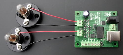
Connect the Lamps to the Controller

Using a screwdriver, connect a lamp to control output 0 of the Phidget motor controller. Connect a second lamp to control output 1. Make sure the wires are connected correctly. In a later step you will add to this circuit.


Figure Circuit for turn signals

Connect the Controller to the Computer

Next plug the USB cable into the Phidget motor controller and into the computer. Have your teacher check that your lamps are wired correctly. Finally connect the power supply to the controller.

Load and Run the Program

Next you will need to load and run a program that will communicate with the Phidget motor controller. Click on the next link and select RUN when the dialog box appears.

Turn Signal Control

Test the program by clicking the left, right, and hazard buttons. You can adjust the flash rate by moving the slider button.


Figure Turn signal control program

Adding an Input Function

The Phidget motor controller has 4 inputs that can be used to communicate with the computer. Leave the circuit set up. In the following steps, you will fabricate a switch system to simulate the turn signals on a car.

A simple switch system can be fabricated using 3 small pieces of insulated wire (anything over 10cm should do), 3 paperclips, and a small piece of foam or soft wood.

Make the Switch

Strip both ends of the wire. Bend the 3 paperclips as shown in the next 2 diagrams and twist the wire securely around the clips. Push the paperclips into the foam (or whatever you have to hold the clips).


Figure Paperclips connected to wire and mounted in wood block

Connect the Switch to the Controller

Connect the wires as shown in the next image. The center paperclip is connected to G (ground), the left paperclip to input 0 and the right to input 1.


Fig 5 Top view paper clip turn signal

Note:

An input is "sensed" by the Phidget when it is connected to G or ground by a wire (or switch).


Figure Wiring diagram

Run the Program and Test the Switches

With the turn signal control program running, turn the center paperclip until it touches the left paperclip. The appropriate light should begin to flash. Try the right paperclip.

When finished with the activity, click the END button.