| Intermediate Technology Education | Control Technology | Design Stage 2 | Topic 6 | Optional Activity 2 |
Battery-Powered Winch
Battery Powered Winch
The video clip below illustrates a simple winch constructed with a small geared motor similar to the one in the tractor kit, and the motor controller from the tractor kit. Only one motor and gearbox set from the two available is used. It is mounted on a small chassis made from plastic. This setup is used for other activities as well.

Video Battery Powered Winch
The Basic Electrical System
The basic electrical system consists of a 3 volt DC motor, a DC power supply (two 1.5 Volt Cells), and a switch that reverses current direction so that the motor direction can be changed. The next 3 images illustrate the circuit. These show what the switch box looks like with all the plastic components removed.
The first image shows the switch elements in the off position. They only make contact with the green wires from the motor. No electricity flows and the motor does not spin.
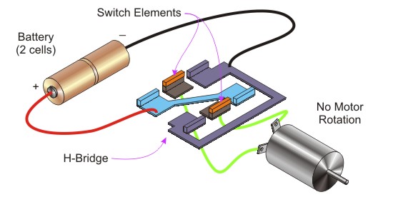
Figure Basic Electrical Circuit Switch in Off Position
The next image shows the switch elements connecting the motor wires to the battery wires. Electricity flows through the circuit and the motor spins. Look at the red wire on the battery and follow the path from it to the motor. Do the same for the black wire on the motor.
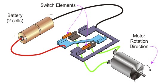
Figure Basic Electrical Circuit Switch in Direction 1
The final image in this series shows the switch elements moved in the opposite direction. AS you did in the previous image, follow the path from the battery through the red wire to the motor, and from the other side of the motor back to the black wire on the battery. The different path causes the electricity to flow through the opposite direction in the motor, so it spins in the opposite direction.
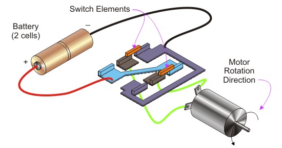
Figure Basic Electrical Circuit Switch in Opposite Direction
The Basic Mechanical System
The mechanical system consists of
- A small DC motor with a gearbox
- A spool to wind the cable on
- A pulley mounted on a column, used to run the cable over in order to lift the load
The Motor/Gearbox
Electric motors are common elements in control systems. Small motors do not have much torque (turning force). Gearboxes provide a mechanical advantage, or a means of getting more torque from a smaller motor. The trade off is reduced speed at the output shaft.
The gearbox used in this example is used to reduce the speed of the output shaft. It does this by using 8 gears. There are 3 sets of double gears, each with a small gear and a large gear. The combination gives the gearbox a reduction of 203:1, meaning that for every 203 revolutions of the motor shaft, the output shaft rotates 1 revolution.
The first image shows the motor with a small spur gear, called a pinion, mounted on the shaft. It meshes with a crown gear and gives a reduction in speed. The crown gear has a smaller gear moulded onto it. That smaller gear meshes with a larger gear, further reducing speed. The larger gear also has a smaller gear moulded onto it.
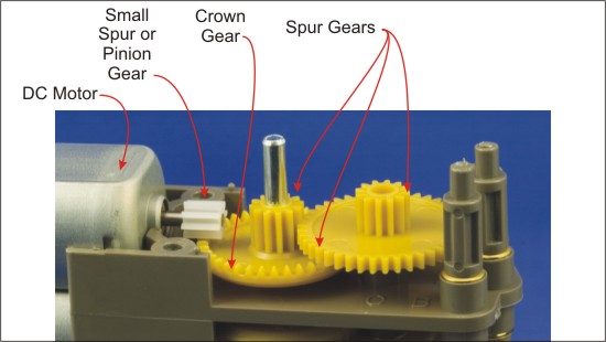
Figure Gearbox Components Part 1
The next image shows a 3rd gear pair added, with a large gear moulded to a smaller gear. As you can see, the large gear is driven by the smaller one that is meshes with, for a further speed reduction.
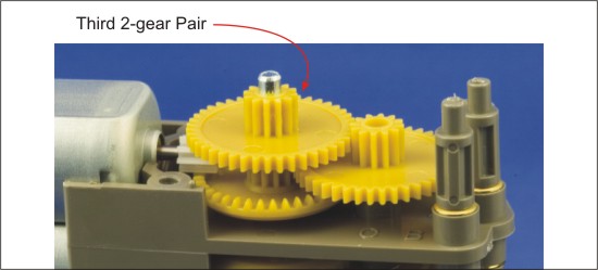
Figure Gearbox Components Part 2
The next image shows the final gear in the gearbox. It is driven by a smaller gear, so gets another speed reduction. It is the output gear, and it has the output shaft attached to it. The output shaft is not affected by the bottom gear, but is driven by the top or final output gear. If you look closely you can see an nut on the shaft that fits into a hexagonal recess on the output gear.
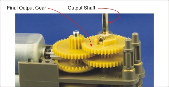
Figure Gearbox Components Part 3
The Cable Spool and the Column
The completed winch requires a spool to wind the cable on and a pulley at the end of a column. The next image is a collage that shows the completed system, as well as close-ups of the parts.
The pulley is a small plastic one mounted on a screw. The plastic will provide significant use before the threads damage it. The take-up spool is an empty thread reel. The motor shaft diameter has been increased by wrapping duct tape carefully around it. This is sufficient for testing a prototype. For more robust use, a spool can be made on a lathe with a hole through the center that is a tight fit.
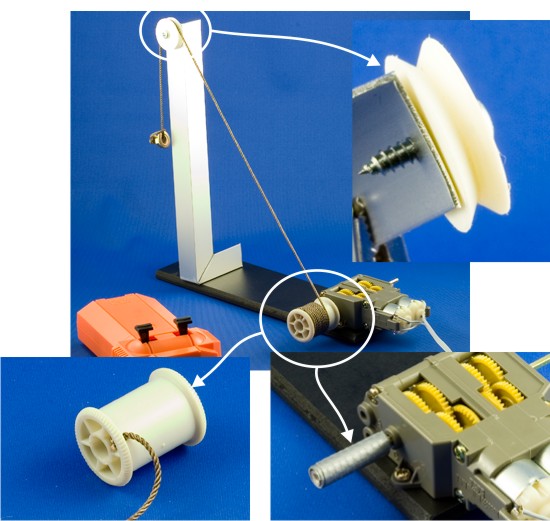
Figure Cable Spool Mounted on the Shaft
For More Information
For more information, check these web pages.
- Plastic Gears
- Gears and Pulleys
- Mechanisms
- Mechanisms
- Electronics. See the topics on motors and switches
- How Gears Work