| Intermediate Technology Education | Control Technology | Design Stage 2 | Topic 6 | Optional Activity 1 |
Pneumatic/Hydraulic Turntable
Linear Motion to Rotary Motion
The following video clip illustrates a simple mechanism to convert linear motion to rotary motion. In this instance motive power is from a pneumatic source. The range of rotary motion is limited to a small arc of a circle. Pay careful attention to the piston that is driving the disk. Notice how it pivots as the arm follows the rotation of the circle.

Video Linear-to-Rotary Motion
The mechanism has two subsystems
- A pneumatic system (or a hydraulic system)
- A mechanical system
The next sections describe how this mechanism was constructed.
The Basic Pneumatic System
The basic system consists of two cylinders connected by tubing. They can be pneumatic or hydraulic. Hydraulic provides more power, and more precise control over the travel of the driven piston. The drawing illustrates the basic system.
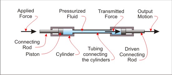
Figure Basic System
The Basic Mechanical System
The basic mechanical system is illustrated in the next two images. As you should have noted in the video, not only does the platform rotate, but the driven cylinder also rotates about a pivot point. To enable that to happen, it is mounted on a rotating carrier plate. Note the location of the pivot point for the carrier plate. The second image shows the carrier plate in a different rotation, corresponding to the end of the connecting rod on the rotating platform.
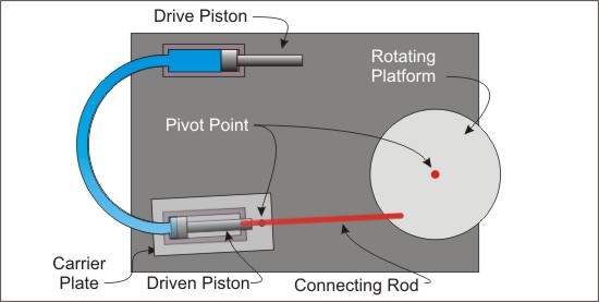
Figure Basic Mechanical System
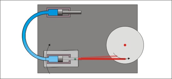
Figure Mechanical System in new Position
Construction of the System
The Pneumatic System
The pneumatic system consists of a pair of cylinders (syringes) connected by a pneumatic line (rubber tubing). It can be converted to a hydraulic system by adding water instead of air. The picture shows the setup.
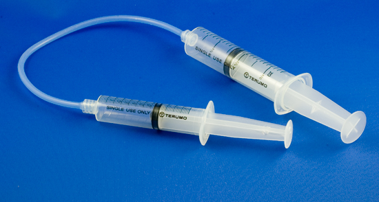
Figure Syringe Pneumatic System
The Mechanical System
The following sequence illustrates how mechanical components were structured.
First a platform was constructed. The one shown in the next image was made from a piece of plastic reclaimed from another project. It shows a mounted syringe holder and two short pieces of red plastic coated coat hanger wire, one slightly longer. They will serve as pivot points, or axles.
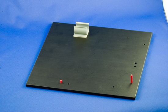
Figure Platform
The next image shows the pneumatic system added to the base, with the drive cylinder mounted in the holder. You should also observe a red connecting rod attached to the piston (syringe). It is made from a piece of red plastic coated coat hanger wire. Holes were drilled in the syringe push rod to attach it.
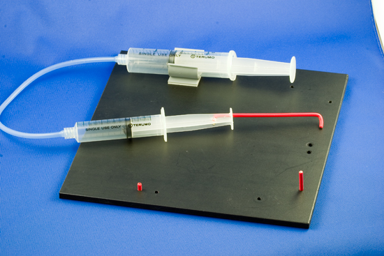
Figure Pneumatics Added
The next image shows a small rectangular piece of plastic added to the right red pivot point. It will serve as a spacer/bearing for the rotating platform. It would probably work better if it was circular.
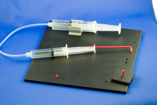
Figure Rotating Platform Bearing Added
The rotating platform was added next. Notice that it is elevated slightly from the base. Also notice the hole near the lower left edge.
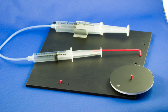
Figure Rotating Platform
The carrier plate for the driven piston is added next. Notice that it has a syringe holder mounted on it. Also notice the pivot pin in the hole just to the right of the syringe holder.
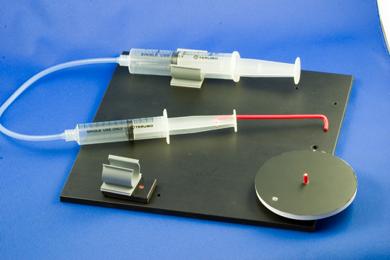
Figure Carrier Plate
The second cylinder (syringe) was mounted in the holder on the carrier plate. In this view, you can clearly see how the red connecting rod is attached.
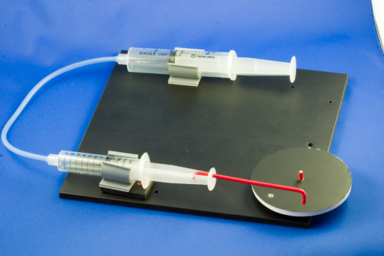
Figure Driven Cylinder on Carrier Plate
Finally the red connecting rod is attached to the rotating platform. As you can see in the next view the piston is at the extreme left position in the cylinder. Note the location of the rotating platform.
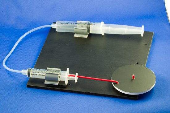
Figure Connecting Rod Attached to Rotating Platform
The final image shows the driven piston extended all the way to its extreme right position.
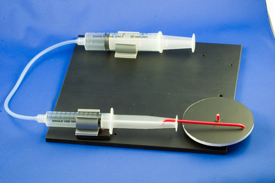
Figure Piston Extended
When the prototype was tested, it was necessary to attach elastic bands to the top of the syringe holders to clamp them more tightly. If you look closely at the video above you will see them.
For More Information
For additional information about how to use syringes for pneumatic and hydraulic systems, check out these websites.
- Syringe Robot Sample Solutions
- Syringe Robots
- Pneumatics
- workshop_instructions Hydraulics and Pneumatics Lifter. Scroll down the page for photos.
- Robot Arm Challenges. Grade 12 projects with photos and videos.
- Robotics.
- Flying Pig Mechanism Demonstrations of how simple mechanisms are created from simple machines.
When you are ready, more to Your Turn