| Intermediate Technology Education | Control Technology | Design Stage 2 | Topic 6 | Knowledge/Skill Activity 2 |
Sketching Technical Drawings—Introduction
- Identify types of lines used in technical drawings
- Sketch lines for technical drawings
- Sketch a series of technical drawings, following standard techniques.
How Technical Drawings are Made.
Technical drawings may be made by
- Freehand Sketching. Done using a pencil and sketching freehand without any other tools
- Creating Mechanical Drawings.
- Can be produced using mechanical drawing tools such as drafting tables, t-squares and triangles.
- Can be produced using computer assisted drawing tools (CAD)
Freehand sketching is by far the quickest method, and with practise can be very accurate and neat. Sketching is generally used for working out ideas, for communicating ideas in real time (demonstrating to someone while they watch), and to make quick drawings of a portion of something when you are fabricating it. Sketching technical drawings is the single most important technical communication skill for working in many technological fields.
Mechanical drawings are more accurate and are used for final drawings. They take much longer to produce and require a high degree of technical skill. Computer-based CAD drawings require a high level of knowledge and skill to use the software.
Regardless of the method used to create the drawings, all technical drawings follow the same rules and protocols. Orthographic and isometric drawings are the primary types used.
Lines used in Drawings
Technical drawing employ different types of lines, each with its own meaning. Placement of the lines on the drawing also has specific meanings. As well, where a piece of the drawing is placed in relation to the rest of the drawing has different meanings. To understand technical drawings, you need to understand this language of lines and and how they are placed on the drawing.
In order for drawings to be easily understood, there are standard ways to create and use lines. Each line has a specific purpose and is always used in the same ways. The basic lines used in technical drawings are listed in the next image. In this example, they are sketched freehand with a pencil.
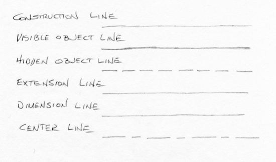
Figure Alphabet of Lines used in Technical Drawings
In the two types of drawings (isometric and orthographic), most lines are either horizontal, vertical, or slanted at 30 degrees. Of course lines can be done at any angle, but these are the most used ones. The next 3 images illustrate this
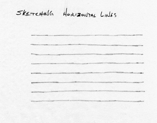
Figure Horizontal Lines
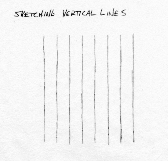
Figure Vertical Lines
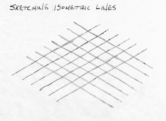
Figure Isometric (30 degree) Lines
Using the Alphabet of Lines
Construction Line
This line is used mainly in sketching, which is a freehand drawing technique. It is a light line drawn with very little pressure on the pencil. It is drawn so that it can easily be erased. Its primary use is to block out sections of the drawing while you are constructing it.
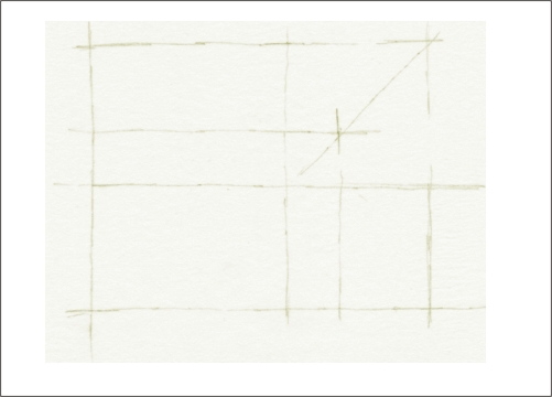
Figure Construction Lines
Visible Object line.
This line is used to draw all the edges of the object. It is a sharp, solid line. You can see it in all the drawings on this page.
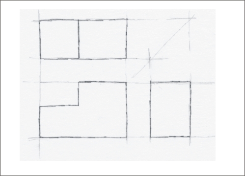
Figure Visible Object Lines
Hidden Object Line
This line is used to show edges that are behind other objects. It is a dashed line consisting of equal length dashes and shorter spaces. It has the same weight as an object line.

Figure Hidden Line (dashed line)
Centre Line (or centreline)
This line is used to show the center line of an object. It consists of a long dash, a space, a short dash, a space and another long dash (repeated). It has the same weight as an object line. In the next drawing a hole has been added to the top drawing. A set of centerlines show its center. Additional hidden lines are added to the two lower drawings to show the hole's passage down through the object.

Figure Center Line
Extension Line
An extension line is used to show where a measurement starts and stops. It lines up with the objects that are being dimensioned. Usually it lines up with the edges of an object and "extends" them beyond the object itself. In the next drawing, extension lines are placed to the right of the top drawing, aligned with one edge and with the center of the hole. Can you spot the extension lines in the lower drawings?
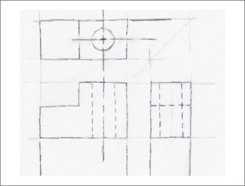
Figure Extension Lines
Dimension Line
A dimension line is used to show the actual measurement. It has an arrowhead on each end. The arrowheads just touch the extension lines. Actual dimensions are written beside the lines.
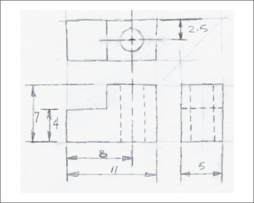
Figure Dimension Lines
When measurements are required they are placed on the Orthographic drawings. Dimensions are not usually placed on the isometric drawings. The next image illustrates typical use of lines in a drawing.
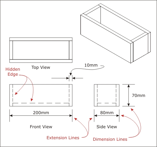
Figure Drawing with Dimensions
There are conventions for putting measurements (called dimensions) on drawings. Conventions are rules that are agreed on by people who do the work. These conventions have evolved over several centuries. Here are a few of the conventions for using lines.
- Extension lines are aligned with the object at the point the measurement is taken.
- Extension lines do not touch the edges of the the object.
- Dimension lines have arrow heads to indicate start and stop points. They touch the extension lines.
- When there is not enough space to put the dimensions, they are placed outside as shown.
- Hidden edges are shown with dashed lines. Hidden edges show edges that are behind other things.
When you are ready, go to Your Turn