| Intermediate Technology Education | Energy and Power Technology | Pre-Design | Topic 3 | Activity 1 |

The Capacitor

Charging a Capacitor

You will need

  • Selection of electrolytic (polarized) capacitors. Suggested values:
    • 1000µf
    • 4700µf
    • 0.33f or 1.0f
  • Owi Solar Battery (2 would be better - borrow one from another group)
  • Switch
  • Digital Multi-meter
  • LED with resistor

Set up the Circuit

Start with a 1000µf capacitor (or the smallest capacitor you have) and

  • Touch its leads together. This will to drain any charge that may be on the plates. Use an alligator clip lead if the leads are too far apart to touch
  • Identify the negative and positive leads of the capacitor (see next illustration). Most capacitors are marked as to which lead is negative. Some have a short and long lead. The short lead is the negative terminal

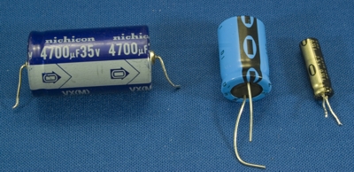
Figure. Three electrolytic, polarized capacitors used in the activity

You will need 2 solar batteries which must be connected in series to give a higher voltage.

  • Identify the positive and negative leads of the solar battery. Connect an alligator lead between the negative terminal of one solar battery and the positive terminal of the second.
  • Connect the circuit as show below. Make sure the switch is open. Use alligator clip leads to simplify the connections.

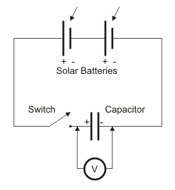
Figure. Schematic circuit for charging capacitor

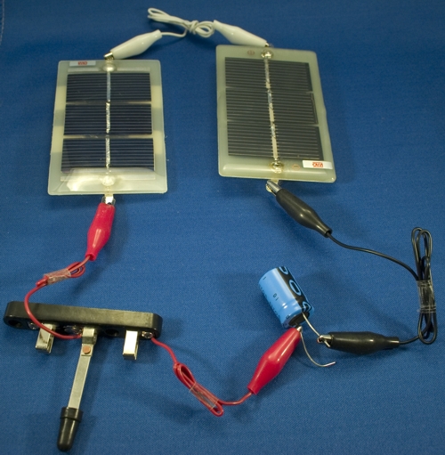
Figure. Charging circuit using 2 solar batteries in series for a higher voltage

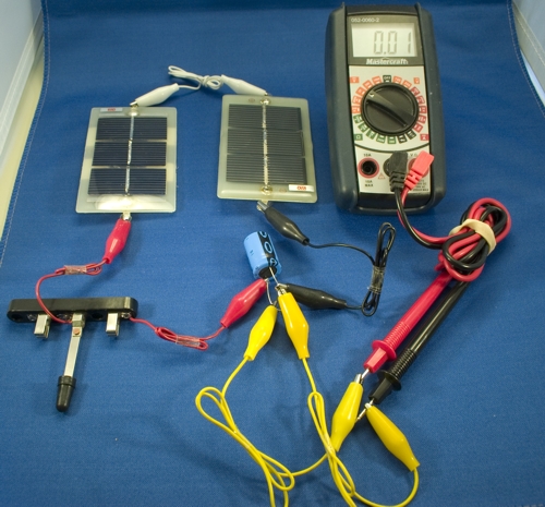
Figure. Charging circuit with multi-meter to monitor voltage

Set the multi-meter probes to measure voltage and set the selector switch to 20 volts DC. Turn on the lights and get ready to charge!

Charge!

  • Watch the multi-meter. Close the switch. If you have it right, the voltage should rise to the level output by the solar batteries and then stop.
  • Record this voltage. Also how long did it take to charge? No measurement needed, just record fast, medium, slow etc.

You will get a better idea when you charge the other capacitors.

Use the Stored Energy

  • After the capacitor is charged, remove it from the circuit. Be careful not to touch the two terminals together (called a short) or you will discharge the capacitor.
  • Using alligator clips, connect the negative terminal of an LED (with resistor) to the negative lead of the capacitor. Look at the LED and touch the LEDs positive lead to the capacitor's positive lead.

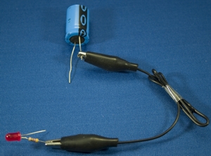
Figure. Testing the capacitors stored charge with an LED

Did the LED turn on? If it did, how long did it turn on for? If it didn't you may have discharged the capacitor or you have the LED backwards.

(If you have time you could try a small motor to see if there is enough charge in the capacitor to turn it over. Small "pager" motors are best!)

Do it Again

  • Repeat step 3 and 4 for each of the other capacitors ending with the largest. That is, the one with the largest capacitance (in the picture above, this was the smallest physically).

Report

In a brief report answer the following:

  • Which capacitor charged quickest?
  • Which capacitor took longest to charge?
  • Which capacitor caused the LED to turn on for the least amount of time?
  • Which capacitor caused the LED to turn on the longest?
  • Is there a relationship between the capacitance of a capacitor, the time it takes to charge and the amount of energy available to run some device such as a LED?

Make appropriate entries in your module portfolio