Using the Oscilloscope Software to Analyze the Trace
The Easyscope software has a built in set of analysis tools that can be
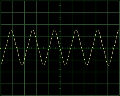
used to measure parameters of the trace. Notice we did not see a couple of
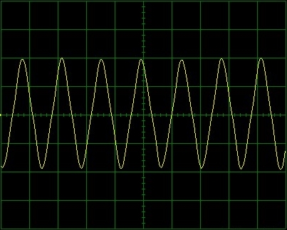
single pulses but instead a series of pulses. This is usually called a wave
train and we refer to its particular shape as a waveform. One single wave
should have a positive and a negative pulse as in the following image.
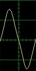
Figure. A Single Waveform
You can find the time it takes to generate one complete wave, also called
the Time Period of the wave by using a set of cursors built into the
software. Click the CursorX button.
Figure. the CursorX Button
When the cursors show up on the oscilloscope display, drag them by
clicking on the blue squares (numbered 1 and 2) to enclose exactly one
complete wave.
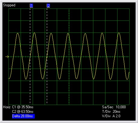
Figure. Cursors Define 1 Wave
Look at the bottom of the display. You will see the time (remember the
x-axis measures time) for the position of cursor 1 and 2 (C1 and C2). The
number highlighted in blue is the Time Period of the wave, that is the time
difference between the positions of C1 and C2. (The word Delta used in
science and technology means "a change in"). In the example above, it is 28
milliseconds or 28/1000 of a second.
- Record your Time Period (Delta) for your report and save the image
to a file.
- Finally, click on the Blue Delta display. It will change to Freq
(Frequency).
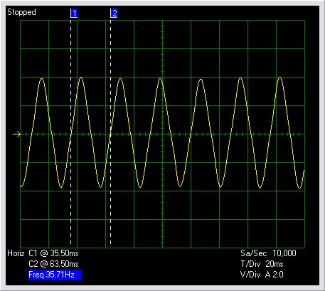
Figure. Frequency
The frequency is how many full waves are produced in one second. The unit
of frequency is named after Heinrich Hertz, a German scientist who made
early discoveries on what we today call Radio Waves. The abbreviation is Hz.
In the example above, the frequency shown is 35.71 Hz or 35.71 waves per
second.
- Record your frequency for your report and save the image to a file.
- Find the electrical information tags / stickers on some pieces of
equipment that plug into an electrical outlet. Can you find the symbol
Hz and if so, what is the number associated with it? Is it the same for
each piece of equipment?
- What determines the frequency of the alternating current? That is
how, can the frequency be changed?
Make appropriate entries in your module portfolio.