| Intermediate Technology Education | Energy and Power Technology | Pre-Design | Topic 3 | Activity 10 |
Electric Circuits
- Identify the functional parts of an electric circuit
- Read schematic drawings for electric circuits
- Make sketches of schematic drawings for electric circuits
- Distinguish between components wired in parallel and components wired in series
Electric Circuits
This activity covers the following
- Circuit components of EMF source, conductors, load, and control
- Electric schematic symbols
- Reading pictorial and schematic drawings
- Sketching schematic drawings
- Components wired in series
- Components wired in parallel
- Measuring EMF (voltage), current (amps) and resistance (ohms) with a multimeter
Circuit Components
An electric circuit is a closed path that electrons can flow through. All electric circuits have four basic components
- EMF source. Electricity requires EMF. The source can be a battery, a photovoltaic panel, or the electric outlet in your room. If it's the latter, the real source may be a hydroelectric generating station, for example.
- Load. The load refers to the device that consumes the energy (converts it to another form). Examples are lights (converts electricity to heat and light) and electric motors (converts electricity to heat and rotary motion).
- Conductors. Conductors are the pathway that electrons follow through the circuit. Examples are wires and copper traces on circuit boards.
- Control. Control is the mechanism that is used to start, stop, and regulate the electric current. Examples are switches and variable resistors (i.e., volume controls)
Drawing Circuits—Pictorial Drawings and Schematic Drawings
A pictorial drawing of a simple circuit is shown below.
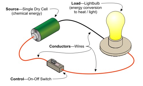
Figure Pictorial of a Circuit showing Components
Most of the time, it is not convenient to make pictorial drawings of electric circuits. Instead, a type of drawing called a schematic is used. From previous activities, you should recall that we use letters as symbols to represent voltage, current, resistance and power. For schematic drawings we use a different set of symbols. A few basic ones are shown below.
Using schematic symbols, the circuit drawn above as a pictorial would look like the figure below. As you can see, the drawing is much simpler. It is also easier to draw, and easier to read.
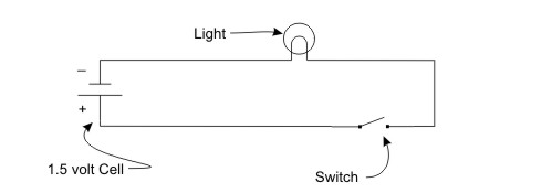
Figure Schematic of Light Circuit
Look at the next schematic. Can you identify the components in the circuit?
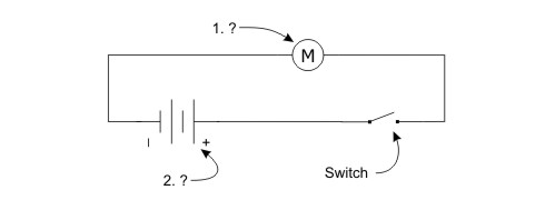
Figure Schematic—Can you identify Item 1 and Item 2?
Circuits with Components connected in Series
The following pictorial shows two lights connected in series. Components connected in series means that electrons flow through one and then the other, losing some of its energy to each one. In the case of the lights, each light will be less bright than if there was only one light in the circuit.
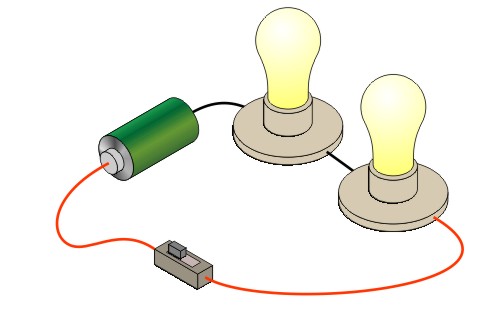
Figure Circuit with Lights connected in Series
As the schematic below shows, the electrons flowing through the circuit have to pass through the two lights in sequence.
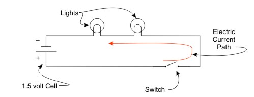
Figure Circuit Schematic Lights connected in Series
Circuits with Components connected in Parallel
The next pictorial shows two lights connected in parallel. There are separate paths for electrons to flow through each light. As a result the lights are full brightness.
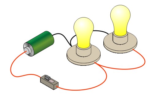
Figure Circuit with Lights connected in Parallel
The parallel circuit schematic shows the two paths for current flow in the circuit.
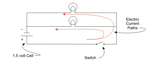
Figure Circuit Schematic Lights Connected in Parallel
Electrical Measurement
The previous activity introduced EMF, current and resistance measurements (voltage, amperes, and ohms respectively). It also showed that the three had the mathematical relationship of
EMF (in volts) = Current (in amps) × resistance (in ohms)
and that this relationship is, in fact, called Ohm's Law.
To measure electrical quantities, we commonly use a multimeter, of the type supplied for this course. If you are unfamiliar with the use of a multimeter, complete the activity Using a Multimeter before completing the remainder of the activity.
For Additional Information
For additional information on these topics, please check these web sites
When you are ready, move to Your Turn