| Intermediate Technology Education | Energy and Power Technology | Design Stage 2 | Topic 6 | Optional Activity 3 |

The Photovoltaic (Solar) Cell

Solar Battery Properties

This activity will require the following:

  • Owi solar battery
  • Incandescent light (100 watt or higher)
  • Multi-meter
  • Gear Motor with Wheel and friction/rubber band
  • Small set of plastic/rubber wheels and axle (Lego?)
  • LEDs (with resistors)
  • Alligator clip leads
  • Meter Stick or measuring tape (centimeters)

Open Circuit Voltage

Use this Record Sheet to record the results of the following actions

  • Set the multi-meter probes to measure DC voltage and set the selector switch to 20 volts.
  • Connect the meter probes to the solar battery terminals using alligator clip leads.
  • Position the lamp 50 cm directly above the solar array.

Solarcell Output Measurement

Figure. Setup to Measure Output of Solar Cell

  • Record the voltage (you can use the record sheet link below).
  • Move to 40 cm and repeat the measurement.
  • Continue taking readings every 10 cm until you reach 10 cm.
    Note: if you are using a 200 watt light or above don't leave the lamp on for more time then is necessary to take a reading when you get closer than 20cm.

Make appropriate entries in your Module Portfolio

Short Circuit Current

Using the same setup as above

  • Move the red multi-meter probe to the current measurement jack (200 ma) and set the selector switch to 200 ma DC.
  • Take three measurements with the light at 30, 20, and 10 cm from the solar array.
  • Record the current in the record sheet.

Make appropriate entries in your Module Portfolio

Convert Light into Movement

  • Use a piece of foam core board or even a piece of cardboard to construct the chassis for a simple solar vehicle. You can come up with your own design or use the Chassis Template

Make appropriate entries in your Module Portfolio

Complete the Vehicle

After you have built a chassis, complete the following

  • Mount the wheel on the gear motor. Using double sided foam tape, mount the gear motor on top of the chassis with the wheel centered in the 1 x 6 cm slot.
  • Mount your axle and wheel set at the other end of the chassis, above or below depending on the type of wheel. (Note: leave room for the solar array)

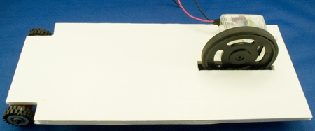
Figure. Mount Axles and Wheels

  • Mount the solar array on the top of the chassis and connect the two leads to the motor leads. Do this by twisting the wires together and using tape or wire nuts to insulate the connection.

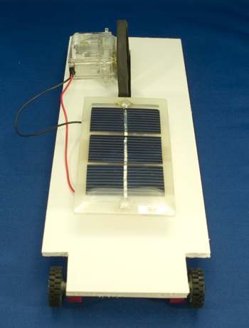
Figure. Mount the Solar Panel

Make appropriate entries in your Module Portfolio

Test the Vehicle

  • Bring the light over the vehicle until it moves. 

Answer the following questions

  • How close did you have to move the lamp?
  • Once the vehicle starts moving, how far did it go (without moving the lamp)?
  • What's the problem with a solar array mounted as it is on this vehicle?

Make appropriate entries in your Module Portfolio