| Intermediate Technology Education | Energy and Power Technology | Design Stage 2 | Topic 6 | Optional Activity 1 |

Wind Generators

Motors as Generators

Collect the following items to start the activity

  • Selection of small DC motors
  • Several plastic propellers (different sizes and shapes)
  • Electric Fan
  • Clamp or lab stand with test tube clamp
  • Alligator clip leads
  • Multi-meter
  • USB Oscilloscope (optional)

Prepare the Generator

Caution: The propeller must be securely attached to the motor shaft. This is usually done using an adapter that "press fits" snuggly or has a set screw that can be tightened. Because the propeller can attain high speeds, never use the apparatus if the 'prop' is not secure.

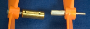
Figure. Examples of Motor Shaft Adapters

Clamp the first motor and propeller and make sure it does not hit anything when it turns. If you are using a lab stand, it's a good idea to use a C-clamp to secure it to a table.

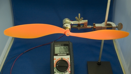
Figure. Model Wind Generator (stand base clamp not shown)

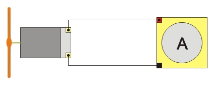
Attach alligator clips to the motor terminals (or leads if there are wires attached to the motor). Set the multi-meter probes to measure voltage and set the selector switch to 20 volts DC.

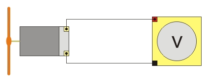
Figure. Block Diagram for the open circuit voltage measurement

Make the Voltage Measurement

The first measurement will be the open circuit voltage measurement. It is called open circuit because there is no load resistance to use any of the energy the generator is producing (the multi-meter consumes only a very small amount). This will be the highest voltage that can be produced!

Wear safety glasses!

Turn on the electric fan and position it in front of the wind generator. Careful, don't put your hands anywhere near the prop - wear gloves if have them.

Watch the multi-meter display. Slowly move the fan until you get the highest reading. Be careful not to come too close. Leave the fan in this position for the rest of the readings.

Leon Vid here maybe??

Use the following table (click the link, open and print the pdf file).

Table

Record the voltage reading in the Motor 1...Open Circuit Voltage cell (shown in gray).

Make the Current Measurement

Fig. Block diagram for the short circuit current measurement

The second measurement will be the short circuit current measurement. It is called short circuit because the multi-meter in current mode has no resistance and all of the current the generator can produce will flow through the meter. Again, this will be the highest current that can be produced! Note that since the generator is producing its highest energy the propeller should run slower.

Move the red multi-meter probe to the current measurement jack (200 ma) and set the selector switch to 200 ma DC.

Put on safety glasses!

Turn on the electric fan and record the current produced in the table in the Motor1...Short Circuit Current cell.

Repeat and Compare

Repeat Step 3 and 4 for each of the other motors. Fill in the table in the appropriate cells. Again, make sure the prop is secure on the motor shaft and that you wear safety glasses.

Switch Props

If you have additional propellers, repeat Step 3 and 4 with a different propeller and each of the motors. Again, fill in the correct cells with the voltage and current.

Analysis

Consult your table and answer the following:

  • Which Motor - Propeller combination gave the highest voltage reading?
  • Which Motor - Propeller combination gave the highest current reading?
  • Why do you think one motor would have a higher voltage output then the others (you need to research what factors increase the voltage output of a generator)?

Reserve the best motor combination (voltage and current) for the next activity